

RS485 vs CAN for Industrial Battery BMS: How OEMs Choose the Right Communication Interface
Choosing between RS485 and CAN for an industrial battery BMS is not simply a matter of comparing communication speed.
The correct choice depends on the OEM equipment architecture, required update rate, network topology, controller support, fault-handling strategy, software resources and diagnostic workflow.
More importantly, an RS485 or CAN connector does not guarantee compatibility. Two devices may use the same physical interface but still fail to communicate because their baud rate, message format, addressing, scaling, timing or application protocol is different.
For OEM engineers, the real question is therefore not only “RS485 vs CAN?” It is:
Which communication architecture can reliably exchange the required battery data and commands throughout the equipment’s operating life?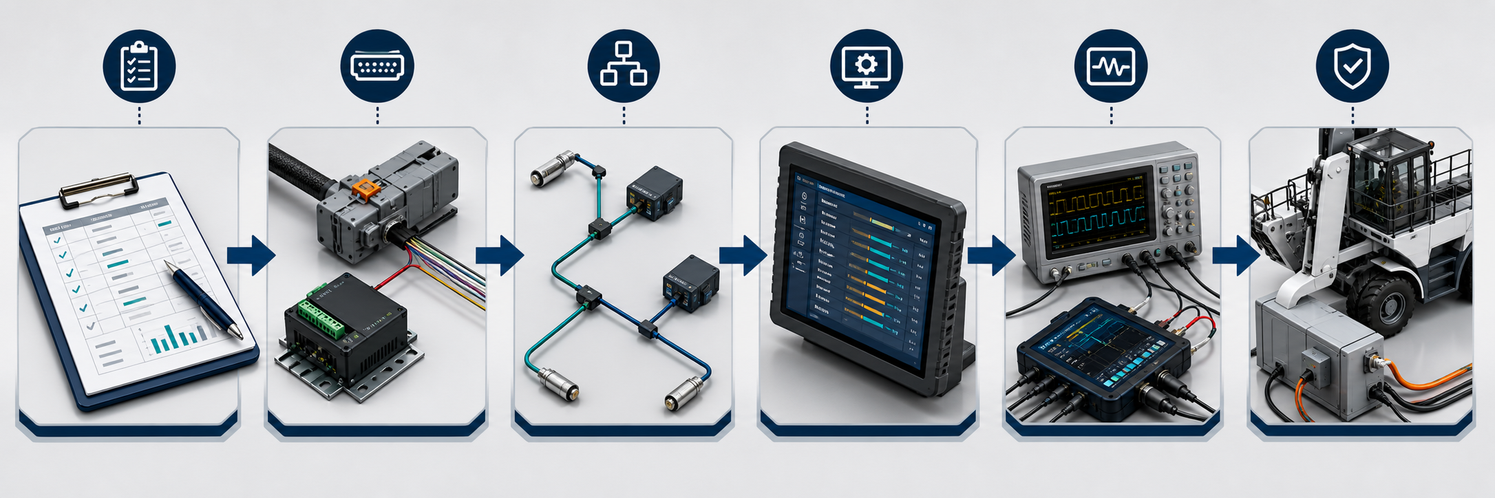
The Short Answer: When Should You Choose RS485 or CAN?
RS485 is often suitable when the system uses a defined master device, relatively predictable polling, moderate update rates and a simple point-to-point or multidrop network.
CAN is often suitable when several controllers need event-driven communication, message prioritization, distributed control, rapid fault reporting or integration with an existing CAN-based machine network.
| Selection factor | RS485 | CAN |
|---|---|---|
| Typical communication model | Master-slave or client-server | Multi-node, message-based communication |
| Common data exchange | Polling and response | Broadcast and event-driven messages |
| Network access | Controlled by the master or application protocol | Message arbitration based on identifier priority |
| Integration effort | Often simpler for basic monitoring | Often better suited to distributed real-time systems |
| Higher-layer protocol | Modbus RTU or proprietary protocol | CANopen, J1939 or proprietary protocol |
| Typical use | Monitoring, configuration and supervisory control | Mobile machinery, robots, AGVs and distributed controllers |
| Main risk | Same RS485 hardware but different serial protocol | Same CAN hardware but incompatible message definitions |
This comparison is only a starting point. The final decision must be based on the equipment’s complete communication requirements.
RS485 and CAN Are Not the Same Type of Specification
One reason RS485 vs CAN discussions become confusing is that the two terms do not describe exactly the same part of a communication system.
RS485 primarily defines an electrical interface for balanced serial communication. It describes how electrical signals are transmitted between drivers and receivers, but it does not define what the data means.
Texas Instruments’ RS-485 Design Guide describes RS485 as an electrical-only standard widely used in industrial applications.
A complete RS485 battery BMS implementation therefore also requires an application protocol, such as:
-
Modbus RTU.
-
A manufacturer-specific register protocol.
-
A proprietary command-and-response format.
-
Another documented serial protocol.
CAN includes a data-link layer as well as defined physical-layer options. The CAN controller handles functions such as frame transmission, arbitration, error detection and acknowledgment. However, CAN still does not automatically define the meaning of battery data.
A CAN bus battery BMS may use:
-
CANopen.
-
SAE J1939.
-
A vehicle or equipment manufacturer’s proprietary protocol.
-
A battery supplier’s proprietary message map.
The CAN in Automation overview explains that CAN’s lower layers are standardized through the ISO 11898 series. Higher-layer protocols are still needed to define how devices exchange application data.
Therefore:
RS485 or CAN defines how data can travel. The BMS communication protocol defines what the data means and how the equipment should respond.
What Information Should the Battery BMS Exchange?
Before selecting an interface, define the information the OEM controller actually needs.
Common BMS data may include:
-
Pack voltage.
-
Charge and discharge current.
-
State of charge.
-
State of health, where supported.
-
Minimum and maximum cell voltage.
-
Battery and cell temperature data.
-
Charge and discharge permission.
-
Recommended current or power limits.
-
Alarm and protection status.
-
Contactor or relay status.
-
Charger connection status.
-
Firmware and hardware version.
-
Fault history or diagnostic information.
-
Remaining energy or runtime estimate.
Some systems also require commands from the host controller, such as:
-
Wake or sleep request.
-
Contactor control.
-
Fault reset.
-
Operating-mode selection.
-
Charging enable or disable.
-
Current-limit request.
-
Service or calibration commands.
Do not assume that every BMS supports all these functions. Each required signal should be classified as mandatory, optional or diagnostic-only.
How RS485 Battery BMS Communication Works
RS485 commonly uses a differential pair to transmit serial data. Depending on the design, it may use a two-wire half-duplex or four-wire full-duplex configuration.
In many battery applications, a host controller, display, gateway or charger acts as the master. It sends a request to a defined battery address, and the battery returns the requested data.
A typical sequence may be:
-
The host requests pack voltage.
-
The BMS validates the address and command.
-
The BMS returns the value and error-checking data.
-
The host requests current, temperature or alarm status.
-
The polling cycle repeats.
Advantages of RS485 for Battery BMS Integration
RS485 can be a practical choice when:
-
The OEM controller already includes an RS485 port.
-
The system has one clear master.
-
Battery information can be collected through periodic polling.
-
The required update rate is moderate.
-
A simple multidrop network is sufficient.
-
Modbus RTU or another documented protocol is already used.
-
The engineering team has serial communication experience.
The official Modbus specifications page provides the current Modbus application protocol and serial-line implementation guidance. Modbus Organization recommends its Serial Line Protocol and Implementation Guide V1.02 for new serial implementations.
Limitations and Risks of RS485
RS485 does not define:
-
Device addresses.
-
Register locations.
-
Data scaling.
-
Byte order.
-
Command meanings.
-
Polling intervals.
-
Timeout behavior.
-
Fault recovery.
-
Security or authentication.
These items belong to the application protocol.
Polling can also create latency. If a controller polls multiple batteries and many registers sequentially, the most important fault message may have to wait until its next scheduled request.
That delay may be acceptable for a monitoring system but unsuitable for a fast control loop. The requirement must be quantified rather than assumed.
How CAN Bus Battery BMS Communication Works
CAN uses message identifiers instead of a simple destination-address model. Devices monitor the shared bus and process the messages relevant to them.
When more than one node attempts to transmit, CAN arbitration allows the higher-priority message to continue without corrupting the winning frame. This makes CAN suitable for systems where several controllers must share time-sensitive data.
The CAN controller also provides built-in frame-level error detection and signaling. These features improve communication robustness, but they do not replace the need for correct system design, wiring and application-level fault handling.
Advantages of CAN for Battery BMS Integration
CAN can be a strong choice when:
-
The machine already has a CAN network.
-
Multiple controllers need battery information.
-
Faults must be reported without waiting for a polling cycle.
-
Different messages need different priorities.
-
The system uses distributed real-time control.
-
The OEM already supports CANopen, J1939 or a defined proprietary protocol.
-
Bus analyzers, DBC files or CAN diagnostic tools are part of the development process.
CAN in Automation lists standardized higher-layer approaches including CANopen and J1939-based profiles. Selecting CAN hardware alone does not determine which of these protocols is being used.
Limitations and Risks of CAN
A CAN port does not guarantee compatibility with another CAN device.
The OEM still needs to confirm:
-
Classical CAN, CAN FD or another variant.
-
Nominal bit rate.
-
Identifier format.
-
Standard or extended identifiers.
-
Message identifiers.
-
Data length.
-
Byte order.
-
Scaling and offset.
-
Transmission period.
-
Event-triggered conditions.
-
Timeout limits.
-
Node startup behavior.
-
Fault recovery.
-
Required higher-layer protocol.
A battery using proprietary CAN messages will not automatically communicate with a controller designed for CANopen or J1939.
RS485 vs CAN Architecture
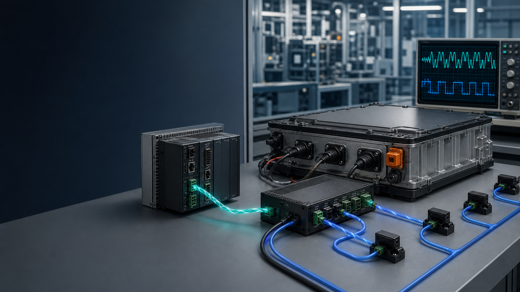
Figure 1. RS485 commonly uses controlled request-response communication, while CAN supports distributed message transmission and identifier-based arbitration. The exact application protocol must still be defined for both.
RS485 vs CAN: Detailed OEM Comparison
Network Topology
RS485 commonly uses a trunk or daisy-chain arrangement with short device branches. CAN also uses a linear bus topology with termination at both ends.
Star wiring should not be assumed safe for either interface. Long branches and uncontrolled cable routing can create reflections and signal-integrity problems.
The permitted topology depends on:
-
Cable length.
-
Bit or baud rate.
-
Stub length.
-
Transceiver characteristics.
-
Termination.
-
Cable impedance.
-
Electromagnetic environment.
Communication Timing
RS485 timing is often controlled by the master’s polling schedule. Engineers can estimate the worst-case data age by calculating:
-
Number of devices.
-
Number of requests per device.
-
Frame length.
-
Baud rate.
-
Response delay.
-
Retry count.
-
Timeout period.
CAN commonly uses periodic or event-triggered transmission. Engineers must instead evaluate:
-
Bus utilization.
-
Message priority.
-
Transmission interval.
-
Worst-case arbitration delay.
-
Error-frame behavior.
-
Timeout monitoring.
Neither architecture is automatically faster in every real system. A well-designed RS485 protocol may outperform an overloaded CAN network, while a properly prioritized CAN system may report critical faults faster than a long polling cycle.
Fault Handling
For RS485, the application normally needs to detect missing responses, invalid checksums, duplicate addresses and communication timeouts.
For CAN, the controller provides frame-level error mechanisms, but the application must still decide what to do when:
-
A required message stops arriving.
-
A node restarts.
-
Data becomes stale.
-
The bus enters an error state.
-
A battery reports a protection alarm.
-
Two devices use conflicting identifiers.
Communication health must be converted into a safe equipment response.
Diagnostics
RS485 diagnostics may use:
-
Serial terminal software.
-
Protocol analyzers.
-
Register-reading tools.
-
Oscilloscopes.
-
USB-to-RS485 adapters.
-
Communication counters and logs.
CAN diagnostics may use:
-
CAN bus analyzers.
-
DBC or EDS files.
-
CANopen or J1939 diagnostic tools.
-
Oscilloscopes.
-
Bus-load analysis.
-
Error counters and message logs.
The service team must receive tools and documentation that match the selected protocol.
The Most Important Compatibility Documents
Before approving an RS485 or CAN battery, request a communication package containing the following items.
1. Interface Definition
-
RS485, Classical CAN or CAN FD.
-
Half-duplex or full-duplex configuration, where applicable.
-
Isolated or non-isolated interface.
-
Connector manufacturer and part number.
-
Pin assignment.
-
Cable and shield requirements.
-
Reference ground requirements.
2. Network Configuration
-
Baud rate or CAN bit rate.
-
Device or node address.
-
Identifier format.
-
Termination requirements.
-
Biasing requirements for RS485.
-
Maximum node count.
-
Recommended cable length and topology.
-
Startup and discovery procedure.
3. Message Dictionary
For each message or register, document:
-
Name.
-
Identifier or register address.
-
Data type.
-
Byte order.
-
Scaling.
-
Offset.
-
Unit.
-
Valid range.
-
Update interval.
-
Read or write permissions.
-
Behavior when the value is unavailable.
4. Alarm and Protection Mapping
Define how the BMS reports:
-
Overvoltage.
-
Undervoltage.
-
Overcurrent.
-
Short circuit.
-
High or low temperature.
-
Communication failure.
-
Contactor failure.
-
Sensor failure.
-
Cell imbalance, where supported.
-
Charging and discharging restrictions.
5. Timeout and Recovery Rules
Specify:
-
When data becomes stale.
-
How many retries are allowed.
-
What the host should do after timeout.
-
How the BMS wakes from sleep.
-
What happens after power cycling.
-
Whether faults clear automatically or require a command.
-
How firmware versions affect compatibility.
Public Dailymag Energy Communication Options
Dailymag Energy’s public product information shows that communication requirements vary by battery configuration.
The published 25.2V 10.2Ah battery page lists RS485 communication.
The published 51.2V 108Ah battery page lists RS485 and CAN communication.
These listings confirm that the physical communication options appear on the published configurations. They do not confirm that a particular Modbus, CANopen, J1939 or proprietary protocol will work with a customer’s controller.
Protocol compatibility, message documentation, connector definition and software behavior must be confirmed for the specific project.
Buyers can review the broader Dailymag Energy product range, but the final interface should be frozen only after technical review.
Eight Questions That Determine the Correct Interface
1. What interface does the existing controller support?
Using an existing controller interface can reduce hardware and software changes. However, protocol compatibility still needs to be confirmed.
2. Is the battery joining an existing network?
If the machine already uses CANopen, J1939 or a proprietary CAN network, adding another CAN device may be logical. If the battery connects only to a display or gateway, RS485 may be sufficient.
3. How quickly must critical data arrive?
Define actual timing requirements for current limits, temperature alarms, low state of charge and protection events.
“Real time” is not a measurable requirement. Specify a maximum acceptable delay.
4. How many devices will share the bus?
Consider batteries, chargers, displays, inverters, controllers, gateways and service tools. The network should be reviewed as a complete system.
5. Who controls communication?
A simple supervisory system may work well with master-controlled RS485 polling. A distributed machine may benefit from CAN’s event-driven communication.
6. What diagnostic tools does the team already use?
Development and service teams may already have Modbus tools, CAN analyzers, DBC workflows or controller libraries. Reusing proven tools can reduce integration risk.
7. How will future versions be managed?
Adding new data fields should not break existing equipment. Define reserved registers, message versioning, compatibility rules and firmware identification.
8. What happens when communication fails?
The equipment needs a safe response when battery data is missing, delayed, implausible or inconsistent.
Do not wait until field testing to define this behavior.
A Six-Stage BMS Communication Validation Process
A reliable integration should pass through controlled engineering stages.
Stage 1: Define Required Data and Commands
Identify every signal the equipment needs. Classify each one as mandatory, optional or diagnostic.
Stage 2: Confirm the Physical Interface
Check transceivers, connector pins, isolation, reference ground, shielding, termination and cable requirements.
Stage 3: Build the Network
Create the intended topology with the real cable length, device count, termination and branch arrangement.
Stage 4: Map the Protocol
Implement identifiers, registers, scaling, byte order, message timing, commands, alarms and timeout rules.
Stage 5: Bench-Test Normal and Fault Conditions
Test:
-
Normal startup.
-
Battery sleep and wake.
-
Controller restart.
-
Missing messages.
-
Corrupted or invalid frames.
-
Incorrect address or identifier.
-
Unplugged cable.
-
Bus short or open circuit.
-
Repeated retries.
-
High bus traffic.
-
BMS protection events.
Stage 6: Validate the Complete Machine
Test the battery, controller, charger and equipment together under representative load, temperature and electromagnetic conditions.
Figure 2. Communication validation should progress from requirements and wiring through protocol mapping, bench diagnostics and complete-machine testing.
Common BMS Communication Failures
Correct Connector, Wrong Pinout
Two products may use the same connector shell but assign power, ground and communication pins differently. A visual match is not evidence of compatibility.
Correct Interface, Wrong Protocol
An RS485 BMS using proprietary commands will not automatically work with a Modbus controller. A CAN BMS using proprietary frames will not automatically work with CANopen or J1939 equipment.
Missing or Incorrect Termination
Improper termination can cause reflections, communication errors or intermittent faults. Verify termination at the network level rather than adding resistors to every device.
Incorrect Data Scaling
A raw value of 512 may mean 51.2 V, 5.12 V or something else depending on scaling. Units, signed values, byte order and offsets must be documented.
Timeout Mismatch
The host may mark data invalid before the BMS’s next scheduled message. Alternatively, the host may continue using stale data for too long.
Wake and Sleep Conflict
The BMS may enter low-power mode while the controller expects continuous communication. Wake sources and timing must be agreed.
Grounding and Electromagnetic Noise
Improper reference grounding, shielding or isolation may create errors even when bench communication appears stable. Test with the actual machine, charger, motor drive and cable routing.
Security Should Be Defined Above the Interface
Do not assume RS485 or CAN automatically provides authentication, encryption or access control.
CAN in Automation notes that the standardized CAN data-link protocols do not inherently provide security measures. Likewise, a basic serial Modbus implementation should not be treated as a secure communication channel merely because it uses RS485.
If unauthorized access or message manipulation is part of the project threat model, define security at the appropriate system layer. Possible controls may include:
-
Authenticated gateways.
-
Network segmentation.
-
Secure service access.
-
Command authorization.
-
Firmware signing.
-
Secure boot.
-
Message freshness checks.
-
Application-layer authentication.
-
Physical access control.
Security requirements should be included in the equipment architecture, not added after protocol integration.
What to Include in an RS485 or CAN Battery RFQ
Provide the battery supplier with:
-
Equipment type and controller model.
-
Required physical interface.
-
Existing network protocol.
-
Baud rate or CAN bit rate.
-
Standard or extended CAN identifier requirement.
-
Required battery signals and update intervals.
-
Commands the host must send.
-
Connector and pinout.
-
Cable length, topology and node count.
-
Isolation, grounding and shielding requirements.
-
Alarm, timeout and safe-state behavior.
-
Required protocol files, test tools and validation support.
If the protocol has not yet been selected, provide the control architecture and timing requirements instead of choosing an interface by habit.
Frequently Asked Questions
1. Is CAN always better than RS485 for a battery BMS?
No. CAN offers useful arbitration, error handling and distributed communication features, but RS485 may be simpler and fully adequate for a master-controlled monitoring system. The correct choice depends on the equipment.
2. Can two RS485 devices communicate automatically?
No. They must use compatible baud rates, wiring and application protocols. Having RS485 ports on both devices does not guarantee compatible commands or registers.
3. Can any CAN battery work with a CAN controller?
No. The devices must use compatible bit rates, identifiers, message definitions, timing and higher-layer protocols.
4. Does RS485 mean Modbus RTU?
No. Modbus RTU commonly uses RS485, but RS485 can also carry proprietary or other serial protocols.
5. Does CAN mean CANopen?
No. CANopen is one higher-layer protocol built on CAN. Other systems may use J1939 or proprietary CAN messages.
6. Which interface is better for AGVs and industrial robots?
CAN is common in distributed mobile machinery, but the answer depends on the existing controller network, latency, diagnostics and integration resources. RS485 may still be suitable for a separate supervisory battery link.
7. What is a DBC file?
A DBC file describes CAN messages, identifiers, signals, scaling and related information. It can help software and diagnostic tools interpret CAN data, but not every proprietary CAN project provides one.
8. Is termination required for both RS485 and CAN?
Both commonly require controlled termination based on the network design. The correct resistance and placement depend on the interface, topology and transceiver implementation.
9. Should the communication interface be isolated?
Isolation depends on grounding, cable length, voltage differences, EMC conditions and system safety architecture. The supplier and equipment engineer should evaluate it together.
10. What should be tested before approving the battery?
Test normal data, timing, alarms, commands, startup, sleep and wake, timeouts, controller restart, cable faults, high traffic, charger operation and representative machine loads.
Choose the Communication Architecture Before Freezing the Battery
The best time to define RS485 or CAN communication is before the battery enclosure, connector and control software are frozen.
Start with the data, timing and fault-response requirements. Then select the physical interface, network topology and higher-layer protocol that match the equipment architecture.
Document every register or message, test the complete network, and define what the machine should do when communication becomes unreliable.
Dailymag Energy supports customized lithium battery pack matching for industrial equipment. If your project requires RS485, CAN or another BMS communication interface, prepare the controller information, protocol requirements, pinout and required data list before requesting a proposal.
Contact the Dailymag Energy engineering and sales team to begin a project-specific communication review.