

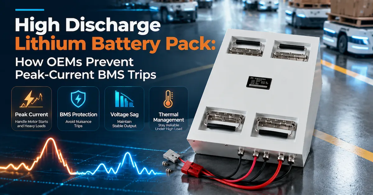
Why Does a High Discharge Lithium Battery Pack Still Trip the BMS?
Direct answer: A high discharge lithium battery pack trips its BMS when the measured electrical or thermal condition exceeds a configured protection limit for the configured time. The trigger may be a real overcurrent, a voltage sag caused by resistance, a hot connector, low state of charge, a cold battery, an overly short protection delay, an incorrect current sensor value or a communication and recovery sequence that the machine does not understand. A high current number printed on a product page does not prove that the complete battery, harness, controller and mission will operate without trips.
This guide addresses a commercial-investigation and RFQ problem for AGV, AMR, robot, industrial vehicle and automation OEMs: how should a buyer specify and validate a high discharge lithium battery pack when motor starts, lifting, acceleration or regeneration cause nuisance protection events? Define the peak event, measure the current path, compare the result with the BMS configuration, correct the cause, then repeat the test on a production-intent sample.
1. Define What High Discharge Means for the Equipment
High discharge is not a single industry-wide number. A 100A event may be severe for a compact robot and ordinary for a larger AGV. The same pack can experience a brief motor-start pulse, a repeated traction load, a long hydraulic lift, or regenerative current flowing back toward the battery. Each event creates a different combination of voltage sag, heat and BMS response.
Describe the load as a time-based event
Write peak current with duration, repetition, starting SOC, temperature and the minimum voltage accepted by the controller. A useful requirement looks like: "The pack shall support the measured traction pulse for the defined seconds, repeated at the defined interval, from the approved SOC window, while pack voltage remains above the controller limit." The values must come from the equipment, not a generic margin.
Separate average, continuous and peak current
Average current supports runtime planning. Continuous current determines sustained heat and conductor loading. Peak current determines whether a motor starts, an actuator lifts, a robot accelerates or a drive controller recovers from a floor transition. A supplier that quotes one maximum current without these distinctions has not yet described the operating boundary.
Include reverse or regenerative current
Braking, lowering a load or decelerating a vehicle can push current into the battery. The BMS may have a different charge-current limit from its discharge-current limit. If the RFQ describes only the positive motor current, it may miss a protection trip that happens during braking. Record direction, duration and frequency for regenerative events.
| Load term | What it describes | Evidence needed |
|---|---|---|
| Average | Typical energy demand over a mission or shift. | Route log, payload, idle time and measured battery power. |
| Continuous | Highest load the pack must sustain for a defined period. | Timed test, temperature, SOC and voltage-sag limit. |
| Peak discharge | Short or repeated positive-current event. | Pulse duration, repetition, starting SOC and controller minimum voltage. |
| Regeneration | Current returned to the pack during braking or lowering. | Reverse-current trace, charge limit and BMS response. |
2. Understand Why the BMS Sees a Trip Before the Controller Does
The robot controller sees the voltage and current available at its own terminals. The BMS sees its sensors and protection logic at a different point in the electrical path. A brief resistance increase at a fuse, busbar, connector or cable can create a local voltage or current condition that is invisible in a coarse controller log. Conversely, a current sensor offset can make a normal event look excessive to the BMS.
Map the measurement points
For the sample test, identify where pack current is measured, where pack voltage is measured, where the controller voltage is measured and where temperatures are recorded. Use synchronized instruments where possible. If the BMS current sensor is in a different path from the external test shunt, explain the difference instead of comparing two numbers as if they were identical.
Check the trigger and the consequence
“BMS trip” can mean a discharge MOSFET opened, a contactor dropped, a charge permission bit changed, a warning alarm was sent, or the controller interpreted a stale communication frame as a battery failure. Record the exact state transition. The corrective action depends on whether the cause is a physical overcurrent, a sensor problem, a configuration problem or a control-integration problem.
Use a fault timeline
Capture at least current, pack voltage, controller voltage, SOC, temperature, BMS alarm state and controller status in one time base. Mark the first threshold crossing, the protection action and the recovery event. This timeline is more useful than a screenshot taken after the robot has stopped.
3. Check the Complete High-Current Path
A high discharge lithium battery pack is a system of cells, parallel and series connections, busbars, fuses, switching devices, cables, connectors and terminals. The weakest part of that path can determine the real peak capability. A current rating based only on the cell data ignores the resistance and heat of the assembled product.
Inspect cells and parallel paths
Ask how the design distributes current across parallel groups and how matching, welding or busbar construction is controlled. The supplier should identify the approved cell or module boundary in the technical file. Do not infer cell brand or chemistry from a product name. Those details require confirmation for the exact configuration.
Inspect busbars, fuses and switching devices
Busbar cross-section, weld quality, fuse selection and BMS switching devices affect voltage drop and heat. A MOSFET path may behave differently from a contactor path during a short pulse, and a fuse may protect a cable while allowing a nuisance trip in a poorly coordinated BMS setting. Ask for the current-path design basis and the conditions used for the rating.
Inspect cables and connectors at the installed length
Measure the voltage at the pack terminals and at the controller during the same peak event. Include connector mating, cable length, bend radius, crimp or lug method and service movement. A connector that is adequate on a bench may heat or loosen in a vibrating vehicle. The battery supplier and equipment maker should agree who owns the harness and terminal specification.
4. Distinguish Voltage Sag From a True Overcurrent
Voltage sag is often blamed on weak cells, but the root cause can be the battery, harness, connector, controller input or measurement method. During a peak event, current rises and resistance produces a temporary drop. If the controller falls below its undervoltage threshold, it may reset. If the BMS also detects an overcurrent or cell undervoltage, two protections can appear at nearly the same time.
Measure at both ends of the path
Use pack-terminal voltage and controller-input voltage in the same trace. The difference shows the drop outside the pack. If pack voltage itself collapses, inspect cell groups, internal busbars, switching devices and BMS settings. If pack voltage is stable but controller voltage falls, inspect the harness, connector and vehicle-side terminals before changing the battery design.
Test at several SOC points
A battery can pass a high-current pulse when full and trip at a lower SOC because resistance and available power change. Test the approved pulse at multiple SOC points, with the intended temperature limits. The acceptance criteria should include minimum voltage, recovery time, temperature and whether the BMS alarm remains clear.
Do not hide sag with an oversized voltage margin
Increasing nominal voltage may mask a harness problem while creating a new controller or charger mismatch. Correct the current path and validate the allowed voltage window first. If a different voltage platform is genuinely needed, update the controller, charger, insulation, enclosure and test plan as one system change.
5. Review BMS Protection Thresholds, Delays and Hysteresis
Protection settings determine whether a transient is accepted, warned, interrupted or latched. The same current can be safe for one duration and unsafe for another. A buyer should request the behavior of the proposed BMS rather than only a headline “maximum discharge” value.
Document each relevant protection item
For discharge overcurrent, record the threshold, delay, release condition, hysteresis, latch behavior and reset method. For cell undervoltage, record the cell threshold, pack response and recovery requirement. For temperature, identify sensor locations and whether charge and discharge use different limits. For short circuit, define the service procedure after a trip.
| BMS behavior | Question for the supplier | Robot acceptance check |
|---|---|---|
| Overcurrent delay | What pulse duration is permitted before the output is opened? | The real motor event completes without a nuisance trip. |
| Hysteresis | What condition must clear before current is allowed again? | The pack does not chatter between run and fault states. |
| Latch and reset | Does the fault auto-recover, require charging or require service? | The operator can recover safely and the controller records the cause. |
| Alarm data | Which message, register or output identifies the event? | The fleet system sees a defined alarm, not an unexplained shutdown. |
Coordinate BMS and controller limits
The controller may require a current pulse that is below the cell capability but above the BMS setting. Alternatively, the BMS may allow the pulse while the controller resets because of voltage sag. The two limits must be compared in one system specification. A safe design is not one where the BMS simply waits longer; it is one where the mechanical, electrical and control limits are coordinated.
6. Account for Temperature and State of Charge
High discharge capability is conditional. Temperature changes resistance, available power, sensor readings and protection behavior. SOC also matters because the same pack may deliver a stronger pulse near full charge than near the lower end of the usable window. A high discharge lithium battery pack should therefore be specified with a temperature and SOC boundary.
Test the cold and hot edges required by the application
Request operating and charging temperature limits for the exact configuration. If the equipment works in a cold warehouse, outdoor yard or hot enclosure, test the peak event after the battery has reached the relevant condition. Do not convert an industry rule of thumb into a Dailymag product promise; the public product pages do not publish a universal low-temperature, high-temperature or thermal-rise specification.
Use the sensor location as evidence
A BMS temperature reading is meaningful only when the sensor is placed where the design risk exists. Check the sensor arrangement around cells, busbars, switching devices and connectors. During validation, record the hottest measured location, not only the value shown in the communication screen.
Define the usable SOC window
Peak-current acceptance may be defined from 80% to 20% SOC, from a dispatch reserve to a return-to-charge threshold, or by another project rule. State the rule clearly. A supplier should not be asked to guarantee a current at “low battery” without a numeric SOC boundary and a minimum voltage.
7. Validate Charging and Regeneration With the Same Rigor
A pack that supports high discharge can still trip during charging or regeneration. The charge path has its own current limit, temperature rule, connector rating and BMS permission. In a robot or AGV, braking energy can arrive at the battery when the SOC is high or the temperature is low, creating a charge overcurrent or overvoltage event.
Check the charger profile
Confirm maximum charge voltage, standard and maximum current, termination behavior, connector polarity, pre-charge or wake sequence and fault recovery. Dailymag's public 51.2V 108Ah robot platform lists 58V charge voltage and 20A standard charge; the public 48V 200Ah AGV platform lists 54V charge voltage and 20A standard charge. These values require confirmation against the controlled datasheet and intended charger before use in a design.
Test opportunity charging and interrupted charging
If the equipment charges between missions, measure the current actually accepted during the available time, including tapering and temperature limits. Remove AC input, open the dock contact, restart the controller and reconnect after a protection event. Record whether charge permission, discharge permission and alarms return in the intended order.
Test regenerative current
Use the real braking or lowering profile. Record reverse current, pack voltage, SOC and BMS charge state. If the vehicle controller limits regeneration, include that limit in the specification. Do not assume that a discharge rating also describes safe charging or reverse-current capability.
Review BMS Communication Integration
8. Use Public Product Data as a Screening Baseline
Public product data can help an engineering team decide whether a platform is worth reviewing. It cannot replace the project data sheet, test method or BMS configuration. The following values are visible in Dailymag's public application products and should be treated as screening evidence.
| Public platform | Listed discharge fields | Project confirmation still required |
|---|---|---|
| 51.2V 108Ah robot | 50A standard discharge; 150A maximum continuous discharge; RS485/CAN listed. | Peak duration, SOC, temperature, voltage sag, BMS settings and protocol. |
| 48V 200Ah AGV | 40A standard discharge; 200A maximum continuous discharge; RS485 listed. | Model voltage, pulse capability, charge behavior, mass, environment and current path. |
| 24V 10h RGV | 2A standard charge/discharge; 20A maximum continuous discharge; RS485 listed. | Product naming, controller window, pulse profile and final charging specification. |
The public pages do not establish a universal cell brand, chemistry, cycle life, IP rating, warranty, thermal curve or certification package. They also do not define a complete peak-pulse test. A buyer should request the latest controlled data sheet, drawing, BMS parameter revision and acceptance test before treating any current value as a release limit.
9. Diagnose a Nuisance BMS Trip in a Controlled Sequence
Replacing the battery immediately can hide the cause. Use a repeatable sequence so the equipment team and supplier can separate load behavior from configuration and assembly problems.
Step 1: reproduce the event
Use the same payload, route, temperature, SOC, charger and firmware. Record the event several times. Note whether the trip occurs at startup, acceleration, lifting, steering, braking, docking or a communication restart.
Step 2: capture the fault timeline
Log current, pack voltage, controller voltage, temperatures, SOC, BMS alarm, controller alarm and communication state. Identify which signal changed first. A BMS trip that follows a connector voltage drop needs a different action from one that precedes a measured overcurrent.
Step 3: inspect the physical path
Check torque or retention, crimp quality, cable routing, connector heating, fuse condition, contactor or MOSFET behavior, insulation and mounting. Inspect for vibration marks or rubbed insulation. Perform the same test with the intended production harness, not a temporary bench cable.
Step 4: compare configuration revisions
Match the sample serial or lot to the BMS hardware, firmware or parameter file, protocol document and test report. A silent parameter change can alter trip timing or SOC behavior even when the enclosure and capacity label look unchanged.
Step 5: retest after one controlled change
Change one factor at a time: harness, connector, BMS parameter, cooling, load sequence or controller setting. Record the effect on safety, voltage, temperature and recovery. Do not approve a change simply because the trip disappeared if the controller still falls below its voltage limit.
| Observed symptom | Possible cause | First evidence to collect |
|---|---|---|
| Trip only at low SOC | Voltage sag, cell imbalance or an SOC window below the design boundary. | Cell and pack voltage, SOC, current and temperature at the event. |
| Trip after repeated cycles | Heat accumulation, connector resistance or insufficient recovery time. | Peak sequence, temperature trend and joint voltage drop. |
| Trip during braking | Regenerative charge current, high SOC or charge protection. | Reverse current, charge permission, SOC and pack voltage. |
| Trip after a software update | Changed BMS limits, current scaling, alarm map or timeout. | Hardware, firmware, parameter and protocol revisions. |
10. Validate the High Discharge Pack on Four Levels
A bench current test is necessary but not sufficient. A production decision should connect component behavior, pack behavior, machine integration and repeat manufacturing.
Level 1: component and assembly evidence
Confirm the approved cell or module boundary, parallel path, busbar or cable design, fuse, switching device, current sensor, connector, temperature sensor and enclosure. Check workmanship, insulation, labels and serial or lot traceability. The exact materials and approved substitutions belong in the controlled BOM.
Level 2: pack electrical test
Measure capacity or energy under a defined method, standard charge and discharge, continuous current, peak pulses, voltage sag, recovery, temperature and protection behavior. Test multiple SOC points and the required temperature range. Store raw data and instrument information with the pack revision.
Level 3: controller and charger integration
Verify startup, current limits, undervoltage response, charge permission, discharge permission, alarms, communication timeout, wake and sleep, regeneration and fault recovery using the intended controller and charger. Confirm the units and scaling of any BMS data.
Level 4: representative mission and pilot lot
Run the robot, AGV or industrial vehicle with the real payload, route, acceleration, lifting, braking and charging pattern. Then build a pilot lot with production-intent materials, work instructions, fixtures, inspections and end-of-line tests. Compare pilot variation with the approved sample before releasing repeat production.
11. Compare a Standard Platform With a Custom High-Discharge Pack
A public platform can shorten development when its voltage window, current capability, dimensions, connector, charger, BMS behavior and environment already fit. Customization is justified when the equipment has a repeated peak event, unusual harness, limited battery bay, special regeneration, private-label requirement or fleet control requirement that a standard pack cannot prove.
| Decision factor | Standard platform may fit when... | Custom design is justified when... |
|---|---|---|
| Peak load | The measured event stays within documented current, voltage and temperature limits. | The event needs a different pulse, recovery, current path or BMS profile. |
| Mechanical fit | Envelope, mass, mounting, cable route and service access are accepted. | The bay, connector orientation, center of gravity or removal method is unique. |
| Control | Existing charger and BMS communication pass the integration test. | The controller needs a defined data map, alarms, permissions or recovery behavior. |
| Supply | Catalog packaging, forecast and traceability meet the program. | The fleet needs a private revision, pilot plan, custom packaging or change control. |
Do not use the word “high discharge” as a substitute for a test condition. A custom pack is valuable when it reduces integration risk and creates a controlled production baseline, not simply because it has a larger current number.
12. Build an RFQ That Prevents a Misleading Current Quote
Send one technical baseline to every supplier. Require each bidder to list assumptions, exclusions and the evidence included with the sample. This makes a quotation comparable and exposes whether the proposed high discharge lithium battery pack has actually been engineered around the equipment.
- Equipment: model, mass, payload, motor or actuator type, route, speed, acceleration, lift, braking and environment.
- Voltage: nominal voltage, permitted operating window, controller minimum voltage, maximum charge voltage and regeneration boundary.
- Current: average, continuous, peak discharge, duration, repetition, starting SOC, temperature and reverse current.
- Energy: shift length, mission cycles, reserve, usable SOC window, opportunity-charge plan and target end SOC.
- Electrical path: fuse, contactor or MOSFET path, cable length, connector, terminal and vehicle-side harness ownership.
- BMS: protection functions, thresholds, delays, hysteresis, alarms, reset behavior, current sensor and temperature sensors.
- Communication: RS485 or CAN, data map, units, update timing, permissions, timeout behavior and protocol owner.
- Mechanical: envelope, mounting, mass, center of gravity, connector location, bend radius, restraint and service removal.
- Validation: sample quantity, load equipment, SOC points, temperature points, robot test, raw data, pass/fail limits and deviation process.
- Commercial: prototype and pilot MOQ, annual forecast, tooling or NRE, packaging, destination, Incoterm and schedule dependencies.
Dailymag's public service information describes product design, sampling, R&D, quality management, packaging, logistics and after-sales support. It also describes planning ranges of approximately 15-30 business days for standard customization and 45-60 business days for projects requiring more R&D and testing. These are planning ranges, not unconditional delivery promises. Request a configuration-specific quotation through the Dailymag contact page with the current log, battery-bay drawing, charger and controller information.
13. Factory Evidence That Supports High-Current Repeatability
Incoming and process control
Ask how cells or modules, BMS boards, busbars, connectors, cables, insulation and enclosure parts are identified and accepted. Review controls for welding or crimping, torque, insulation, sensor placement, BMS loading, labeling and end-of-line current tests. Dailymag publicly describes quality management from raw-material transportation through preprocessing, production and before shipment, plus sampling checks at four production stages. Convert those statements into evidence for the exact configuration rather than treating them as a generic test report.
End-of-line testing
Define which checks apply to every pack and which use sampling. For a high discharge pack, useful production records may include polarity, voltage, insulation, communication, current-limit behavior, alarm state, charge and discharge permissions, label, serial number and final visual inspection. The exact test limits must be agreed in the approved production file.
Traceability and change control
Link the delivered pack to the model, revision, BOM boundary, BMS hardware, firmware or parameter file, serial or lot and production test record. Require notification and revalidation for a cell, module, busbar, connector, fuse, BMS parameter, firmware, cable, enclosure or charger change that can affect current, temperature, voltage, communication or shipping.
14. Common Mistakes That Cause Repeat BMS Trips
- Choosing a pack from nominal voltage and Ah without measuring the motor-start or lift event.
- Using the maximum continuous current as if it were an unlimited peak current for every duration and SOC.
- Testing the battery with a short bench cable while the machine uses a longer, smaller or vibrating harness.
- Comparing BMS current to controller current without mapping sensor locations and sampling timing.
- Increasing protection delay without checking cell voltage, conductor heating and controller safety.
- Ignoring regenerative current because the battery is described as a discharge product.
- Testing only at high SOC and room temperature while the fleet operates at low SOC or cold temperature.
- Changing BMS parameters or firmware without retesting SOC, alarms, permissions and recovery.
- Approving a sample that starts the machine but has not completed the representative duty cycle.
- Accepting a generic certificate or test record that does not identify the final pack revision.
Open items are manageable when they have an owner, a measurement and a release gate. They become supply risk when an assumption is hidden inside a current number or a "minor change" bypasses revalidation.
Frequently Asked Questions
What is a high discharge lithium battery pack?
It is a rechargeable battery system configured to deliver a defined high-current load for a defined duration and repetition while remaining within its voltage, temperature, protection and mechanical limits. The term does not describe one universal current value. The cells, parallel paths, busbars, BMS, fuse, switching devices, cables and connectors all affect the result.
Why does a high-current pack trip only during acceleration?
Acceleration may create a short current pulse that is much higher than average demand. Voltage sag, connector resistance, low SOC, cold temperature or a BMS delay that is shorter than the real event can trigger protection. Capture current, pack voltage, controller voltage, SOC, temperature and the BMS alarm in one timeline.
Does a 200A maximum continuous rating mean the pack can deliver any 200A pulse?
No. The public 200A value on the AGV-oriented platform must be interpreted with the test conditions, temperature, SOC, voltage sag, current path, protection settings and duration. It should not be copied as a universal design current without project confirmation.
Can a larger cable prevent BMS trips?
A correctly sized cable and connector can reduce external voltage drop and heat, but it cannot correct every cause. The trip may originate in the cell groups, BMS sensor, current configuration, temperature, charge or regeneration path. Change one controlled factor and repeat the complete test.
Should the BMS overcurrent delay simply be increased?
No. A longer delay may prevent a nuisance trip, but it can also expose the cells, switching devices, cables or machine to an unsafe event. The correct delay must be coordinated with the measured pulse, current path, temperature, controller behavior and protection objective.
How does SOC affect high discharge performance?
At lower SOC, available voltage and power can change, and voltage sag may become more significant. Define the approved SOC window for the peak-current test and record the minimum voltage and recovery. A rating proven only near full charge is incomplete for a fleet that operates near reserve.
Does RS485 or CAN prevent BMS trips?
Communication does not prevent a physical overcurrent, but it can help the controller receive warnings, permissions and fault information. RS485 or CAN must be validated with the message map, units, timing, alarms, timeout and recovery behavior of the intended controller.
What factory documents should accompany a high-discharge sample?
Request the controlled specification, drawing, BOM boundary, BMS hardware and parameter revision, current-path description, charger requirement, protection test results, communication document, sample serial or lot, production test plan and change-control rules. Ask that raw test data identify the sample and conditions.
How long can a customized high-current battery project take?
Dailymag's public service information describes approximately 15-30 business days for standard customization and 45-60 business days for projects requiring more R&D and testing. The final schedule depends on design completeness, materials, sample quantity, test scope, buyer approvals, packaging and shipping. Confirm it in the project quotation.
What should I send before requesting a quote?
Send the equipment model, load log or motor data, peak event and repetition, voltage window, runtime and reserve, charger, battery-bay drawing, harness and connector details, environment, required BMS data, sample quantity, forecast, destination and acceptance tests. Mark unknown values as unknown so the supplier can separate measurements from assumptions.
Conclusion
A high discharge lithium battery pack should be approved from a measured system requirement, not from a single current number. The real peak capability depends on the cells, parallel paths, busbars, BMS switching devices, fuse, cables, connectors, temperature, SOC, charger, controller and protection timing. Preventing BMS trips requires a fault timeline, voltage measurements at both ends of the path, defined thresholds and recovery behavior, repeated SOC and temperature tests, and a production-intent validation.
Dailymag's public AGV and robot platforms provide a starting point for matching application, voltage class and current direction. Its public services cover design, sampling, R&D, quality management, packaging, logistics and after-sales support. Final approval should rely on the exact configuration, controlled BMS parameters, representative load profile, traceable sample records, pilot repeatability, agreed MOQ and lead-time assumptions, and a written change-control process.
For an engineering review, send the current waveform or motor data, battery-bay drawing, cable and connector information, charger, controller, temperature range, SOC window, peak-event definition, quantity plan and destination. The Dailymag contact page can route the requirements to the appropriate technical and quotation review.