

Why a Lithium Battery Shuts Down Under Load: Voltage Sag, Peak Current and BMS Protection
The battery display says 62%. The equipment starts normally. Then the drive motor accelerates, a hydraulic pump engages or an inverter wakes up—and the machine suddenly goes dark.
A few seconds later, the battery voltage appears normal again.
This kind of failure is often blamed on insufficient capacity. Sometimes a larger battery is ordered immediately. Yet capacity may not be the real problem.
When a lithium battery shuts down under load, the cause is more often connected to instantaneous current, temporary voltage depression, a weak cell group, BMS protection settings or resistance somewhere in the power path.
The battery may still contain plenty of energy. It simply cannot deliver the required power under that specific condition without crossing a protection threshold.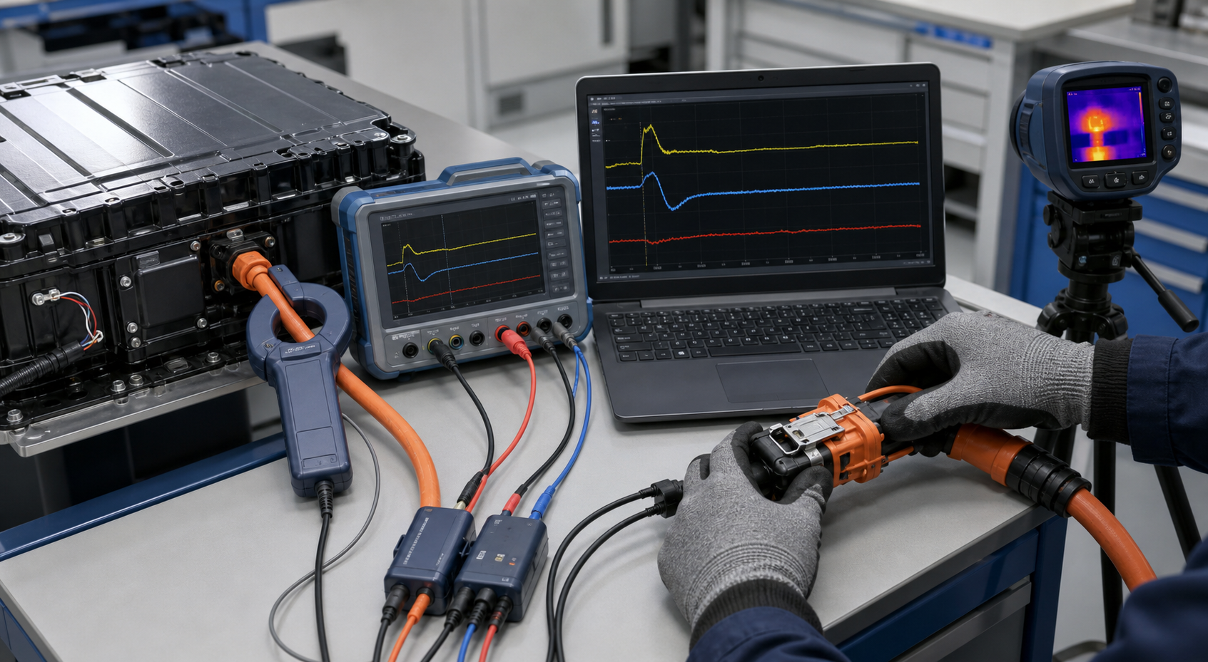
The Short Answer
A lithium battery can shut down under load even when its state of charge looks healthy because the equipment’s demand is not constant.
Motors, compressors, pumps, actuators and inverter inputs can draw a short but substantial current pulse. During that pulse:
-
Cell voltage falls because of internal resistance.
-
Additional voltage is lost through busbars, fuses, contactors, cables and connectors.
-
One cell group may reach the BMS undervoltage threshold.
-
Current may exceed an overcurrent or short-circuit threshold.
-
The BMS opens the discharge path to protect the battery.
-
Once the load disappears, voltage recovers and the fault seems to vanish.
That sequence explains why an open-circuit voltage measurement can look normal immediately after a shutdown.
Capacity and Current Are Different Requirements
A battery specification usually contains several numbers that answer different questions.
| Parameter | What it tells the engineer |
|---|---|
| Ampere-hours | How much electric charge the battery stores |
| Watt-hours | Approximate stored energy at nominal conditions |
| Continuous discharge current | Current the pack is designed to deliver continuously under defined conditions |
| Peak discharge current | Higher current that may be permitted for a limited time |
| Peak-current duration | How long the temporary current is allowed |
| BMS overcurrent threshold | The current level at which protection may begin |
| Protection delay | How long the threshold can be exceeded before disconnection |
| Minimum equipment voltage | The lowest voltage at which the controller or inverter remains operational |
A 100Ah battery does not automatically supply any current the machine requests. Likewise, two batteries with the same capacity may behave very differently during motor starting.
One may use a cell configuration, busbar design, BMS and connector suitable for high current. The other may be designed primarily for longer runtime at a moderate load.
Capacity answers, “How long might it run?”
Current capability answers, “Can it survive this load event?”
Both questions matter.
What Battery Voltage Sag Under Load Really Means
A battery has an open-circuit voltage when little or no current is flowing. Once a load is applied, its terminal voltage falls.
A simplified first estimate is:
Voltage drop = Current × Total resistance
The total resistance is not limited to the cells. It can include:
-
Cell internal resistance.
-
Cell interconnections.
-
Busbars.
-
Current-sense components.
-
Protection MOSFETs or contactors.
-
Fuse resistance.
-
Internal wiring.
-
Output terminals.
-
External connectors.
-
Positive and negative cables.
-
Ground or return connections.
Texas Instruments explains in its Battery Gauging Algorithm Comparison that loaded voltage depends on state of charge, temperature, current and battery resistance. The same publication notes that temperature-compensated resistance becomes especially important at low temperatures.
Even a resistance that looks small on paper can become important during a large current pulse.
For example, suppose the complete battery-to-controller path has 40 milliohms of effective resistance.
At 20A:
Voltage drop = 20A × 0.040Ω = 0.8V
At 100A:
Voltage drop = 100A × 0.040Ω = 4V
The resistance has not changed, but the fivefold increase in current creates a fivefold increase in voltage drop.
If the battery is already partly discharged, cold or aged, that 4V drop may be enough for the inverter to reset or for one cell group to cross its undervoltage limit.
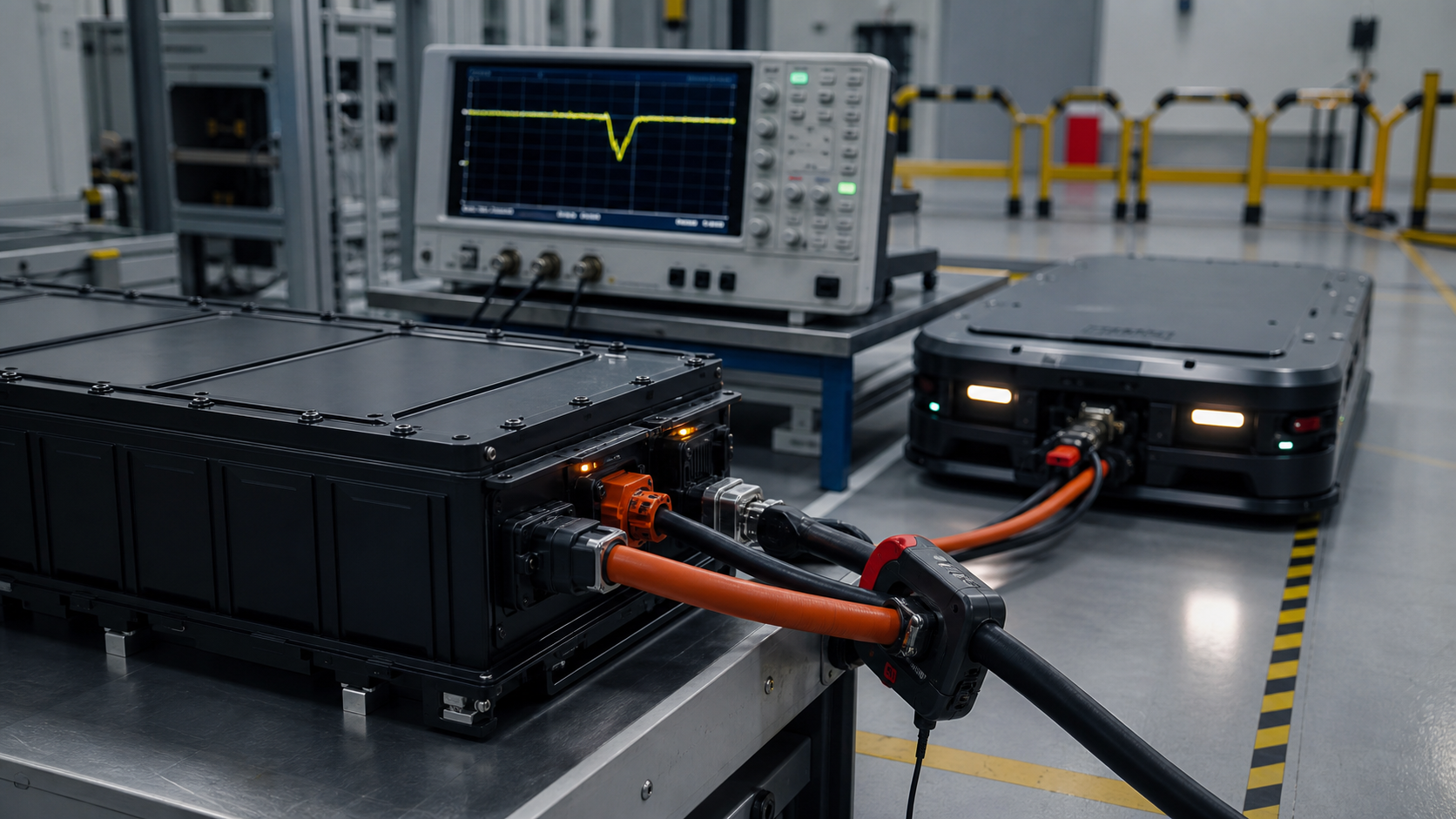
Figure 1. A shutdown can originate inside the cells, at the BMS or anywhere along the high-current path between the battery and the load.
Why Motor and Inverter Loads Expose the Problem
A battery-powered machine rarely draws the same current throughout its operating cycle.
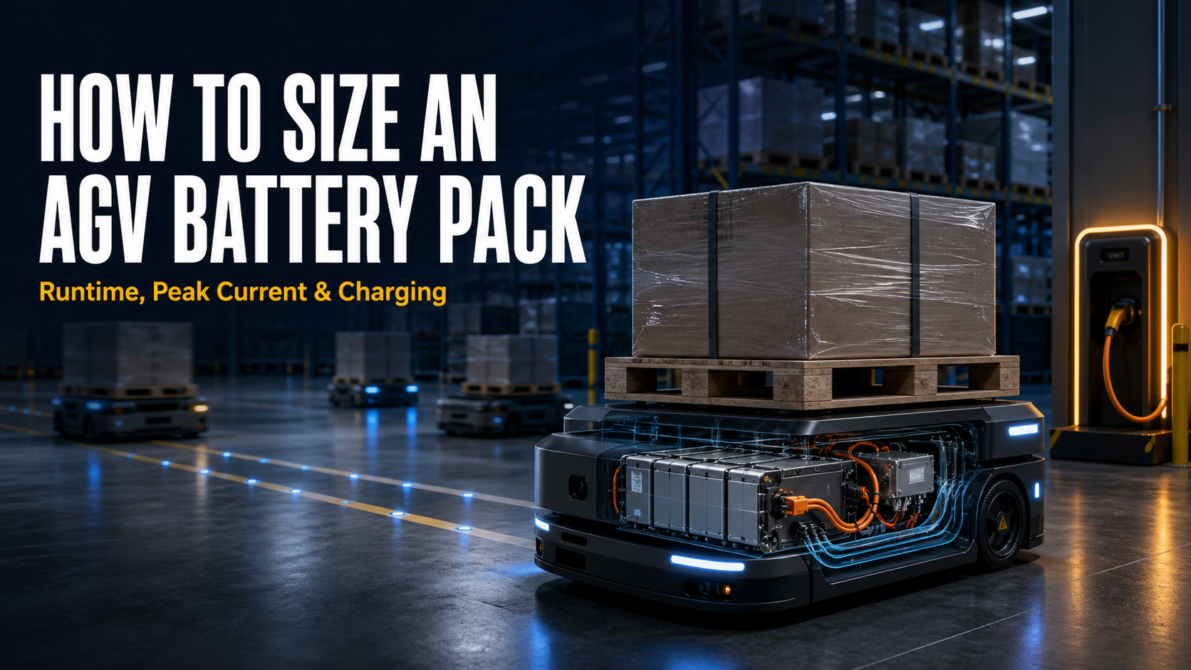
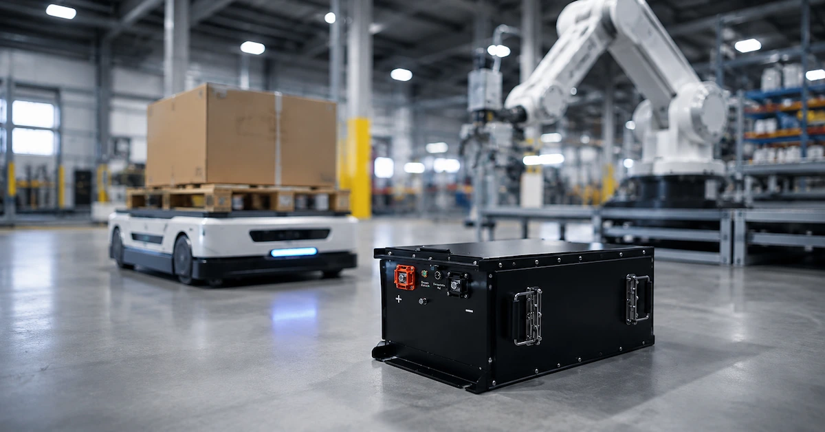
An AGV may cruise at a moderate current but demand much more when it accelerates from rest. A robot arm can produce a short regenerative event in one movement and a high discharge pulse in the next. A compressor may be relatively easy to run once it reaches speed but difficult to start.
Consider a simplified 48V machine requiring 3.6kW during startup:
Current = Power ÷ Voltage
At 48V, the theoretical current is:
3,600W ÷ 48V = 75A
If the bus falls to 42V while the controller is trying to maintain power, the current could approach:
3,600W ÷ 42V = 85.7A
This simplified calculation ignores conversion losses, but it shows the feedback problem: lower voltage can produce higher current demand, which can cause still more voltage drop.
The equipment may therefore operate normally at idle and fail only during:
-
Motor startup.
-
Rapid acceleration.
-
Hill climbing.
-
Steering while accelerating.
-
Simultaneous actuator movement.
-
Pump engagement.
-
Compressor startup.
-
Heater activation.
-
Inverter pre-charge.
-
Recovery from a mechanical stall.
An average-current value will miss many of these events.
Seven Common Reasons a Lithium Battery Shuts Down Under Load
1. Cell Resistance Produces Excessive Voltage Sag
Every cell has internal resistance. That resistance is affected by cell design, temperature, state of charge, ageing and operating history.
Under a high-current pulse, the loaded voltage of every series group falls. If all groups remain above the permitted limit, the equipment continues to operate. If one group falls below the BMS threshold, the pack may disconnect.
This can happen while the pack-level voltage still appears reasonable.
The useful diagnostic value is therefore not only the total pack voltage. Engineers should also capture the lowest cell-group voltage during the event.
A weak group often reveals itself as a much deeper voltage dip than the others, followed by a rapid recovery when the load disappears.
2. The BMS Overcurrent Threshold Is Too Close to the Real Load
BMS overcurrent protection generally depends on both current and time.
A brief current pulse may be acceptable. The same current sustained for longer may trigger protection. A much higher short-circuit current should usually produce a faster response.
Texas Instruments’ documentation for a two-tier battery overcurrent protection circuit illustrates this engineering principle: different thresholds and delays can distinguish a temporary surge from a more severe fault.
That does not mean every BMS uses the same logic. It means that asking only for “maximum current” is incomplete.
The project needs to define:
-
Continuous current.
-
Expected peak current.
-
Peak duration.
-
Repetition rate.
-
Overcurrent threshold.
-
Trigger delay.
-
Short-circuit threshold.
-
Recovery method.
-
Temperature derating.
-
MOSFET, contactor and fuse limits.
A battery peak current of 150A for one second is not equivalent to 150A for thirty seconds.
3. One Cell Group Reaches Undervoltage First
The pack voltage is the sum of all series groups. A single weak or poorly balanced group can cross the lower limit before the rest of the battery is empty.
Possible contributors include:
-
Capacity variation.
-
Resistance variation.
-
Uneven self-discharge.
-
Temperature differences inside the enclosure.
-
Cell connection resistance.
-
Measurement-wire faults.
-
Incomplete balancing.
-
Long periods without a full balancing opportunity.
-
Ageing concentrated in one part of the pack.
After shutdown, the weak group may recover enough that a static reading no longer looks alarming. Time-synchronized BMS data is far more useful than a measurement taken several minutes later.
4. The Cable or Connector Is Consuming the Voltage Margin
A battery can perform correctly at its own terminals while the equipment receives inadequate voltage.
High resistance may be introduced by:
-
An undersized cable.
-
Excessive cable length.
-
Loose bolted connections.
-
Poor crimping.
-
Worn removable connectors.
-
Damaged contact surfaces.
-
Corrosion.
-
Fuse-holder resistance.
-
A weak ground return.
-
Too many adapters between the battery and controller.
Fluke’s guidance on diagnosing voltage drops emphasizes that restrictions are best identified by measuring voltage drop while current is actually flowing. An unloaded resistance check can miss a fault that becomes obvious under operating current.
The practical approach is to measure at two locations simultaneously:
-
Battery output terminals.
-
Controller or inverter input terminals.
If the battery voltage remains acceptable while the controller voltage collapses, investigate the path between them.
5. Inrush Current Is Mistaken for Running Current
Some equipment contains large DC-link capacitors. When the battery is first connected, those capacitors can draw a sharp inrush current.
Other loads create similar short events:
-
Motor magnetization.
-
Transformer input.
-
Capacitive filters.
-
Multiple controllers starting together.
-
Contactors closing without a pre-charge stage.
An ordinary multimeter may show only the settled current and miss the pulse entirely.
The BMS, however, can respond to a millisecond-scale event. The user sees a battery that “will not start the machine,” while the actual failure occurred before normal operation began.
The solution may involve coordinated pre-charge, controlled contactor sequencing or an appropriate BMS delay. Raising protection limits without analyzing the circuit is not a safe substitute.
6. Low Temperature Increases Resistance
A pack that works indoors can behave differently after spending a night in a cold warehouse.
At lower temperature, battery resistance generally rises. The same current therefore causes a deeper voltage drop. Available discharge capability and SOC-estimation accuracy may also change.
The resulting pattern is often confusing:
-
The battery appears charged.
-
The machine starts with no load.
-
The first strong acceleration causes a shutdown.
-
Performance improves after the battery warms.
Low-temperature testing should reproduce the real soak condition. Moving a cold battery into a warm laboratory and waiting before testing may remove the very condition being investigated.
Charging limits at low temperature must be treated separately from discharge performance and confirmed for the selected cell system.
7. The SOC Display Is More Confident Than the Data Justifies
State of charge is an estimate, not a direct measurement of stored energy.
A gauge may combine current integration, open-circuit voltage, temperature and an internal battery model. Accuracy can be affected by:
-
Incorrect design-capacity settings.
-
Unlearned battery parameters.
-
Cell chemistry mismatch.
-
Current-sensor offset.
-
Ageing.
-
Incomplete charge or discharge learning.
-
Long storage.
-
Dynamic loads.
-
Temperature changes.
-
Communication timing.
A display showing 40% does not guarantee that every cell group still has enough voltage margin for a high-current event.
When a lithium battery shuts down under load, the displayed SOC should be treated as one data channel—not the final diagnosis.
How to Tell Which Protection Actually Triggered
The shutdown pattern often provides an early clue.
| Observed behavior | Likely areas to investigate |
| Pack output disappears completely | BMS trip, contactor opening, fuse or connection failure |
| Pack voltage remains present but controller resets | External voltage drop or controller undervoltage |
| Failure occurs only during startup | Inrush current, short peak-current allowance or pre-charge issue |
| Failure occurs near low SOC | Cell voltage sag, weak group or SOC estimation error |
| Failure occurs mainly in cold conditions | Higher cell resistance or temperature-related current limits |
| Connector becomes warm | Contact resistance, crimp or terminal problem |
| Pack restarts after charger connection | BMS recovery logic or undervoltage recovery condition |
| Fault appears after ageing | Increased resistance, capacity loss or connector deterioration |
| Only one machine fails with the same battery | Equipment load, cable, firmware or controller threshold |
| Several batteries fail on the same machine | Machine-side demand or integration problem |
These are starting points, not proof. A fault record and synchronized waveforms are still needed.
A Practical Diagnostic Sequence
The fastest investigation usually begins with waveforms, not component replacement.
Step 1: Reproduce the Exact Event
Record the machine state when the shutdown occurs:
-
SOC.
-
Battery temperature.
-
Ambient temperature.
-
Load action.
-
Travel speed.
-
Slope or mechanical resistance.
-
Attached accessories.
-
Time since charging.
-
Software and firmware versions.
“Failed during use” is too vague. “Failed at 38% SOC during simultaneous lift and acceleration after a six-hour cold soak” is actionable.
Step 2: Capture Current and Voltage Together
Measure:
-
Battery current.
-
Voltage at the battery output.
-
Voltage at the equipment input.
-
Lowest cell-group voltage, if available.
-
BMS alarm and protection flags.
The recording rate must be fast enough to capture the event. A display that updates once per second may completely hide an inrush or protection pulse.
Step 3: Determine Who Opened the Circuit
Do not assume the battery caused every shutdown.
Confirm whether:
-
The BMS opened its discharge MOSFETs.
-
A battery contactor opened.
-
The machine contactor opened.
-
The inverter reset on undervoltage.
-
A fuse or breaker operated.
-
A connector temporarily lost contact.
-
Communication logic commanded a shutdown.
The distinction changes the entire troubleshooting path.
Step 4: Compare Battery-Terminal and Load-Terminal Voltage
Measure the voltage difference across each part of the power path while current flows.
Useful test points include:
-
Cell stack to pack output.
-
Pack output to fuse.
-
Fuse to contactor.
-
Contactor to connector.
-
Connector to controller.
-
Controller ground to battery negative.
A thermal camera can help locate heating, but temperature alone does not replace a voltage-drop measurement.
Figure 2. Capture current, battery-terminal voltage and load-terminal voltage during the same event before dismantling the system.
Step 5: Read the BMS Event Data
Request logs or live data for:
-
Overcurrent in discharge.
-
Short circuit.
-
Pack undervoltage.
-
Minimum cell voltage.
-
Cell-voltage difference.
-
MOSFET or contactor state.
-
Battery temperature.
-
Current-sensor value.
-
Protection timestamp.
-
Recovery status.
The fault flag should be matched to the waveform. A log entry by itself may describe the final protection state without revealing the original cause.
Step 6: Repeat Across SOC and Temperature
A pack may pass at full charge and fail at 30% SOC. It may pass at room temperature and fail after a cold soak.
Test at the boundaries that matter to the equipment:
-
High, medium and low SOC.
-
Minimum intended operating temperature.
-
Maximum intended current.
-
Longest peak duration.
-
Repeated peak events.
-
Aged or representative production batteries.
Testing only a fully charged new sample at room temperature creates false confidence.
Step 7: Verify the Corrected System
Once the cause is identified, repeat the complete operating cycle. Do not stop after one successful startup.
Confirm:
-
Protection is not being bypassed.
-
Cables and connectors remain within their thermal limits.
-
The weakest cell group retains adequate margin.
-
The inverter does not reset.
-
Communication remains stable.
-
Repeated peaks do not create progressive heating.
-
The recovery behavior is safe and predictable.
What the Published Current Rating Does—and Does Not—Tell You
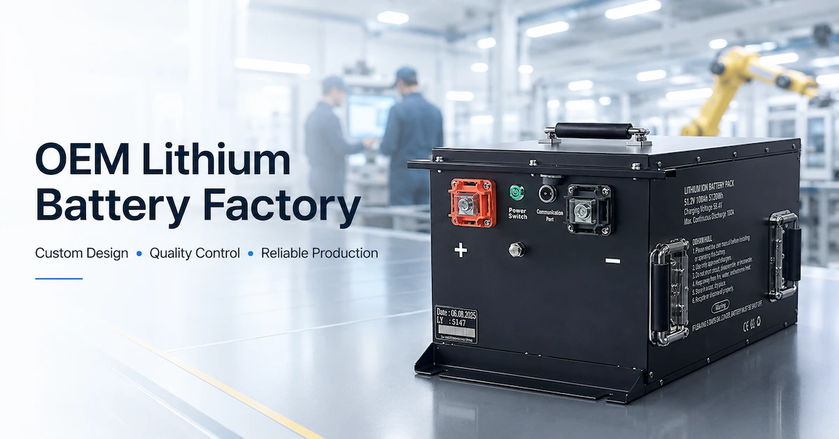
Dailymag Energy’s public product pages demonstrate why current capability must be checked separately from capacity.
The published 25.2V 10.2Ah battery page lists a maximum continuous discharge current of 20A.
The published 51.2V 108Ah battery page lists a maximum continuous discharge current of 150A.
Those are useful screening values, but they do not answer every high-load question.
A project-specific review should still confirm:
-
Permitted peak current.
-
Peak duration.
-
Time between peaks.
-
BMS threshold and delay.
-
Low-temperature derating.
-
End-of-discharge performance.
-
Cable and connector limits.
-
Cooling conditions.
-
Required recovery behavior.
The larger current rating on a product page should not be interpreted as automatic compatibility with a particular motor or inverter.
Buyers can review the broader Dailymag Energy product range, then provide the actual load profile for engineering assessment.
What to Include in a Battery Peak-Current Requirement
A statement such as “the motor is 3kW” is not enough.
A useful battery RFQ should include:
-
Nominal system voltage.
-
Controller operating-voltage range.
-
Controller undervoltage threshold and delay.
-
Average operating current.
-
Maximum continuous current.
-
Peak current waveform.
-
Peak duration.
-
Peak repetition rate.
-
Motor or inverter model.
-
DC-link capacitance or inrush information.
-
Pre-charge arrangement.
-
Cable length and cross-section.
-
Connector and fuse details.
-
Minimum operating SOC.
-
Minimum battery temperature.
-
Required runtime.
-
Regenerative current, if applicable.
-
Communication and fault-response requirements.
-
Required recovery behavior after protection.
-
Representative machine test cycle.
A current waveform is more valuable than a single peak number. It shows how fast the load rises, how long it remains high and whether several events occur close together.
Design Changes That May Solve the Problem
The correct change depends on the measured cause.
Possible engineering responses include:
-
Selecting cells with lower resistance or higher rate capability.
-
Increasing the number of parallel cells.
-
Revising busbar or internal connection design.
-
Selecting an appropriately rated BMS.
-
Coordinating overcurrent thresholds and delays.
-
Adding or correcting a pre-charge circuit.
-
Using shorter or larger cables.
-
Improving crimping and connector selection.
-
Reducing unnecessary adapters.
-
Changing motor-controller acceleration ramps.
-
Staggering simultaneous loads.
-
Revising the equipment undervoltage strategy.
-
Improving thermal management.
-
Correcting SOC and battery-model parameters.
The safest fix is the one that addresses the measured limitation without weakening necessary protection.
What Not to Do
Do Not Bypass the BMS
A shutdown is a symptom and a protective action. Bypassing the BMS removes information and may remove the device preventing cell damage or an unsafe current condition.
Do Not Raise the Current Threshold Blindly
A higher threshold can increase stress on cells, MOSFETs, contactors, busbars, fuses, cables and connectors. The entire current path must be reviewed.
Do Not Diagnose the Pack from Open-Circuit Voltage Alone
Voltage recovery after the load disappears is expected. The important voltage is the value during the load event.
Do Not Assume a Larger Ah Rating Automatically Fixes the Issue
A larger-capacity battery may reduce resistance if it also uses more parallel cells, but capacity itself is not proof of peak-power capability.
Do Not Parallel Unmatched Packs as a Quick Experiment
Parallel battery operation requires compatible voltage, SOC, current sharing, protection behavior, connection resistance and system design. An improvised parallel connection can create new risks and obscure the original fault.
Frequently Asked Questions
Why does the battery voltage return after the equipment shuts down?
When the current disappears, the voltage drop caused by internal and external resistance also decreases. Cell polarization begins to relax, so the terminal voltage rises. This recovery does not prove that the battery was sufficiently powerful during the event.
Can a fully charged battery still trip on undervoltage?
Yes. A severe current pulse, high resistance, a weak cell group or a poor connection can temporarily push voltage below a protection or controller threshold even at a relatively high SOC.
Is battery voltage sag under load always a cell problem?
No. The voltage loss may come from cells, busbars, protection devices, a fuse, cables, connectors or the equipment ground path. Measure at more than one location.
What is the difference between peak current and continuous current?
Continuous current is intended for sustained operation under defined thermal conditions. Peak current is allowed only for a specified duration and repetition pattern. Both must be stated with their operating conditions.
Why does the machine work with its wheels lifted but fail on the floor?
With the wheels lifted, mechanical resistance and required torque are much lower. Floor operation creates higher motor current, especially during startup and acceleration.
Why does the fault appear at low temperature?
Lower temperature can increase battery resistance, causing a deeper voltage drop for the same current. Temperature may also affect current limits and SOC estimation.
Can software solve a peak-current shutdown?
Sometimes. A controlled acceleration ramp, staggered load sequence or correct pre-charge routine may reduce the peak. Software cannot repair a weak connector or make underrated cells safely deliver unlimited current.
What data should the BMS provide during testing?
At minimum, request pack current, pack voltage, individual cell-group voltages, minimum and maximum temperature, protection flags, MOSFET or contactor status and timestamps.
How can I distinguish a BMS trip from an inverter reset?
Record the battery output and inverter input simultaneously, then review BMS status. If battery output disappears, the battery-side protection path probably opened. If battery voltage remains but the controller restarts, investigate external voltage drop and controller thresholds.
Is maximum continuous discharge current enough for battery selection?
No. Equipment with motors, pumps, compressors or capacitive inputs also needs a defined peak-current profile, allowable duration and protection coordination.
Diagnose the Waveform Before Changing the Battery
When a lithium battery shuts down under load, the percentage on the display is rarely enough to explain what happened.
Capture the current pulse. Measure voltage at both ends of the power cable. Check the lowest cell group. Read the BMS protection record. Repeat the test at the lowest intended SOC and temperature.
That evidence separates four very different problems:
-
The cells cannot support the load.
-
The BMS protection does not match the load profile.
-
The power path is losing too much voltage.
-
The equipment controller is reacting to a temporary condition.
Dailymag Energy provides lithium battery pack matching and customization for industrial equipment. For a meaningful technical review, send the motor or inverter information, synchronized load waveform, operating-voltage limits, cable details, temperature range and required runtime.
Contact the Dailymag Energy engineering and sales team to review the battery peak current and shutdown behavior for your equipment.