



24V vs 48V Lithium Battery Packs: How OEMs Choose the Right System Voltage
A battery voltage decision often looks simple at the beginning of an equipment project. The engineering team estimates the required runtime, checks the available installation space, and chooses either a 24V or 48V battery.
The consequences appear later.
A motor controller reaches its current limit during acceleration. A connector runs warmer than expected. The charger does not match the battery’s actual upper voltage. An auxiliary pump still needs 24V, although the main power bus has moved to 48V. In another case, the electrical system works, but the machine controller cannot interpret the battery management system’s CAN messages.
These are not isolated battery problems. They are system-voltage problems.
The right choice in a 24V vs 48V lithium battery comparison depends on peak power, average energy consumption, cable length, voltage drop, controller compatibility, charging strategy, auxiliary loads, communication requirements, and the machine’s future development path.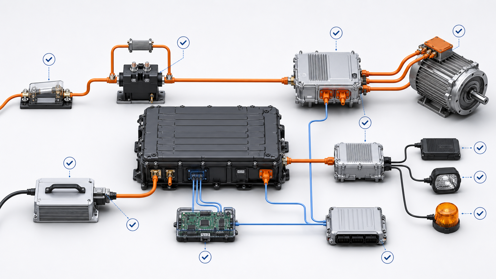
The Short Answer
A 24V lithium battery pack is often a practical choice for compact equipment, moderate-power loads, shorter cable runs, and machines built around an established 24V component ecosystem.
A 48V lithium battery pack—including systems commonly described as 51.2V nominal—is often more suitable when the machine needs higher continuous or peak power, lower current for a given power level, longer wiring runs, or additional room for future performance upgrades.
Neither voltage is automatically better.
| Engineering consideration | 24V platform often fits | 48V/51.2V platform often fits |
|---|---|---|
| Equipment power | Low to moderate | Moderate to high |
| Current at equal power | Higher | Lower |
| Cable and connector burden | Greater as power rises | Easier to manage at higher power |
| Existing component ecosystem | Common in legacy and compact equipment | Common in larger mobile and industrial equipment |
| Auxiliary 24V devices | Can connect directly if voltage range matches | Usually require a DC-DC converter |
| Upgrade potential | May become current-limited | More electrical headroom |
| Integration complexity | Often simpler for existing 24V machines | Requires a complete voltage-compatibility review |
| Typical decision driver | Simplicity and compatibility | Power delivery and reduced current |
The correct decision should be made from an operating profile, not from voltage alone.
“24V” and “48V” Are System Names, Not Complete Specifications
One of the most common sourcing mistakes is assuming that every battery described as 24V has the same operating voltage.
It does not.
The battery chemistry, series-cell count, state of charge, BMS limits, and charge strategy determine the actual voltage window. A “48V” lithium-ion pack and a 51.2V lithium iron phosphate pack may belong to a similar equipment class while having different full-charge, discharge-cutoff, and controller requirements.
For example, eDailyMag lists a compact 25.2V 10.2Ah lithium battery with 257.04Wh of nominal energy, a 20A maximum continuous discharge rating, and RS485 communication. The product belongs to the general 24V system family, but its stated nominal voltage is 25.2V.
At the larger end of the range, the company’s 51.2V 108Ah battery is specified with a 150A maximum continuous discharge rating and RS485/CAN communication.
These products illustrate the breadth of the two voltage classes. They are not direct, equal-energy alternatives.
Before selecting a battery, obtain at least these three voltage values:
-
Nominal battery voltage.
-
Maximum charge voltage.
-
Minimum permitted discharge voltage under the intended load.
The motor controller, charger, DC-DC converter, contactors, capacitors, and other connected electronics must tolerate the entire operating window—not merely the voltage printed in the product name.
Why Higher Voltage Reduces Current
The basic relationship is:
Power = Voltage × Current
For an ideal 2,000W electrical load:
-
At 24V, current is approximately 83.3A.
-
At 48V, current is approximately 41.7A.
Doubling the voltage approximately halves the current required to deliver the same power.
Real equipment is more complicated. Battery voltage changes with state of charge and load, while motors, controllers, pumps, and inverters have efficiency losses. Current during startup or acceleration may also be several times the steady operating value.
Even so, the calculation shows why system voltage becomes increasingly important as machine power rises.
A 10A difference may be easy to manage. A 50A or 100A difference affects cables, terminals, busbars, fuses, contactors, PCB copper, heat generation, enclosure layout, and service procedures.
Current Changes More Than Cable Size
Electrical loss in a conductor can be estimated using:
Power loss = Current² × Resistance
Suppose the total resistance of the positive and negative high-current path is 10 milliohms, or 0.01Ω.
For the simplified 2kW example:
-
At 24V and 83.3A, cable-path loss is approximately 69.4W.
-
At 48V and 41.7A, cable-path loss is approximately 17.4W.
The current has been reduced by half, but the resistive loss falls to approximately one-quarter.
This I²R relationship is also described in the US Department of Energy’s DC Microgrid Scoping Study. Although the study addresses a wider power-distribution context, the underlying conductor-loss principle is the same.
At equal power, a higher-voltage system normally carries less current, reducing resistive heating throughout the high-current path.
Voltage drop follows Ohm’s law:
Voltage drop = Current × Resistance
Fluke’s explanation of Ohm’s law provides a useful foundation for diagnosing these relationships in an electrical circuit.
With the same 0.01Ω path:
-
The 24V example drops approximately 0.83V.
-
The 48V example drops approximately 0.42V.
The higher-voltage system therefore has both a smaller absolute drop and a much smaller percentage drop.
Victron Energy’s Wiring Unlimited technical guide gives a similar practical comparison: a 2,400W load draws 100A at 24V but only 50A at 48V, with substantially lower percentage voltage drop in the 48V example.
The important detail is that resistance is not limited to the cable itself. It accumulates across:
-
Battery terminals
-
Cable lugs and crimps
-
Connectors
-
Fuses and fuse holders
-
Contactors
-
Current shunts
-
Isolation switches
-
Busbars
-
PCB connections
A poorly crimped terminal can erase part of the expected advantage. Voltage selection and connection quality must therefore be engineered together.
Voltage Alone Does Not Determine Runtime
Another frequent mistake is comparing batteries only by ampere-hours.
Battery energy is approximately:
Watt-hours = Nominal voltage × Ampere-hours
Consider two simplified packs:
-
24V × 100Ah = 2,400Wh
-
48V × 50Ah = 2,400Wh
Their nominal energy is approximately equal even though their ampere-hour ratings are different.
If two packs both have a 100Ah rating, the 48V pack stores roughly twice the nominal energy of the 24V pack. It will normally contain more cells and may be larger, heavier, and more expensive.
Runtime should therefore be estimated from usable watt-hours and the machine’s duty cycle. A practical estimate must also account for:
-
Battery discharge limits
-
Cell temperature
-
Conversion efficiency
-
Auxiliary power consumption
-
Aging allowance
-
Required reserve capacity
-
Peak-load behavior
-
Whether the machine can complete its duty cycle before charging
A useful specification does not say only “the machine needs eight hours.” It describes what the machine does during those eight hours.
Peak Load Can Decide the Voltage Before Runtime Does
Average energy consumption may appear modest while peak current is severe.
A mobile robot, cleaning machine, lifting platform, or automated cart may experience simultaneous loads from traction, steering, lifting, pumps, brushes, computers, sensors, and communication hardware. Starting torque, ramps, tight turns, carpet transitions, or lifting events can create short high-current demands.
At lower system voltage, the same peak power requires more current. That can produce:
-
Larger voltage sag
-
Earlier controller undervoltage alarms
-
BMS overcurrent protection
-
Connector heating
-
Contactor stress
-
Reduced available motor torque
-
Unexpected shutdown despite remaining battery capacity
This is why a battery should be selected against both continuous and peak-load profiles.
Ask the equipment team for measured current data if a prototype exists. If it does not, build a load table that includes each subsystem’s continuous power, startup power, duration, and probability of operating simultaneously.
When a 24V Platform Makes Sense
A 24V architecture remains a strong option when it fits the machine rather than constraining it.
It may be the better choice when:
-
The equipment has moderate power demand.
-
High-current cable runs are short.
-
Existing controllers, actuators, pumps, and chargers are designed for 24V.
-
The installation envelope favors a compact battery.
-
Direct support for 24V auxiliary loads simplifies the design.
-
Maintaining compatibility with an established product family is commercially important.
-
Service teams already stock suitable 24V components.
The advantage is often system simplicity.
If the required current remains comfortably within the ratings of the battery, BMS, connector, fuse, contactor, and controller, raising the system voltage may add cost without delivering a meaningful operational benefit.
However, the decision needs margin. A 24V system that operates close to its current limit in normal conditions may have little tolerance for cold cells, aged connectors, motor stalls, future accessories, or higher-performance software settings.
When 48V or 51.2V Becomes Attractive
A higher-voltage platform is often justified when current—not energy—is becoming the main design constraint.
Typical reasons include:
-
Higher traction or motor power
-
Longer cable runs
-
Frequent acceleration or lifting peaks
-
Multiple motors operating together
-
High-power pumps, compressors, heaters, or inverters
-
Excessive cable or connector size in a 24V design
-
A need to reduce voltage drop
-
Future plans for faster movement or higher payload
-
A product platform covering several machine sizes
The lower current at equal power can make thermal management and power distribution easier, but a 48V architecture is not automatically smaller or lighter. The final result depends on energy capacity, chemistry, enclosure construction, protection hardware, and mechanical requirements.
OEMs must also decide whether the platform is truly 48V nominal or 51.2V nominal and validate every component against the full voltage range.
A 24V-to-48V Change Is Not a Battery Swap
Replacing a 24V battery with a 48V battery without redesigning the connected system can damage equipment or create a serious safety risk.
The following components require review:
| Component | What must be checked |
| Motor | Voltage rating, speed, insulation, thermal limits |
| Motor controller | Minimum and maximum DC input, current rating, regenerative behavior |
| Charger | Chemistry, series-cell count, charge profile, maximum voltage, communication |
| DC-DC converter | Input range, output voltage, peak auxiliary load |
| Fuse | DC voltage rating, interrupt capacity, current-time curve |
| Contactor | Coil voltage, contact voltage, continuous current, breaking capacity |
| Pre-charge circuit | Resistance, energy rating, timing, controller capacitance |
| Connector | Voltage, continuous current, mating cycles, environmental sealing |
| Cable | Conductor area, insulation rating, temperature, routing |
| BMS | Cell configuration, current limits, protection logic, protocol |
| Machine controller | CAN/RS485 hardware, message format, alarm and state logic |
| Service equipment | Isolation process, diagnostic tools, technician training |
The machine’s regenerative energy path also deserves special attention. During braking or load lowering, the controller may return energy to the battery. If the battery is cold, nearly full, or unable to accept the regenerative current, bus voltage can rise rapidly.
The BMS, controller, and braking strategy need coordinated limits.
Changing system voltage affects the entire power path, auxiliary supply, charger, protection system, and machine communication—not just the battery.
Remember the Auxiliary Loads
A machine may use a 48V traction bus while most control hardware still operates at 24V or 12V.
Possible auxiliary loads include:
-
PLCs and industrial computers
-
Sensors
-
Cameras and scanners
-
Lighting
-
Fans
-
Solenoid valves
-
Access points and communication modules
-
Pumps
-
Displays and user controls
A properly selected DC-DC converter can supply these loads from the main battery. Its design should consider the complete input-voltage window, peak output demand, isolation requirements, electromagnetic compatibility, efficiency, standby consumption, and startup behavior.
Do not size the converter from the average auxiliary load alone. Several devices may start simultaneously, and some computers or radios have brief input-current peaks.
Communication Compatibility Is Separate from Voltage Compatibility
The presence of RS485 or CAN on both the battery and the machine does not guarantee communication.
The physical interface is only one layer. Successful integration also requires agreement on:
-
Baud rate
-
Node addressing
-
Message identifiers
-
Byte order and scaling
-
State-of-charge definition
-
Alarm and fault codes
-
Charge and discharge limits
-
Heartbeat timing
-
Startup and shutdown sequence
-
Termination resistance
-
Behavior after communication loss
For example, eDailyMag’s 48V 46.2Ah battery lists RS485 communication, while the larger 51.2V product lists RS485 and CAN. That information helps narrow the options, but the OEM still needs the protocol document and a bench-level handshake test.
Voltage fit, connector fit, and protocol fit should be treated as three separate approval gates.
A Practical Selection Process
1. Define the real operating profile
Record average power, continuous maximum power, peak power, peak duration, duty cycle, operating temperature, charging window, and required service life.
Separate measured information from estimates.
2. Calculate the current at both voltage levels
Use the lowest expected battery voltage when checking maximum current. Include controller and conversion losses rather than relying on ideal power equations alone.
3. Build the resistance budget
Estimate resistance through the complete high-current loop, including cables, connectors, fuses, contactors, shunts, crimps, and busbars.
Calculate both voltage drop and I²R heating at continuous and peak current.
4. Compare complete architectures
Do not compare battery quotations in isolation. Include:
-
Battery and BMS
-
Charger
-
DC-DC converter
-
Controller
-
Contactors and pre-charge circuit
-
Fuses
-
Connectors
-
Cable assembly
-
Cooling or heating
-
Mechanical mounting
-
Software integration
-
Certification and validation
A battery with a lower purchase price can lead to a more expensive electrical architecture.
5. Verify the voltage window
Confirm nominal voltage, full-charge voltage, normal discharge range, protective cutoff, transient limits, regenerative conditions, and charger tolerance.
6. Test the communication protocol
Use a real battery or BMS simulator to test normal status messages, limit commands, warning states, communication timeout, restart behavior, and fault recovery.
7. Validate the worst credible condition
A system that works at room temperature with a new battery is not yet validated.
Test combinations such as:
-
Low temperature plus peak acceleration
-
Low state of charge plus lifting
-
High temperature plus continuous operation
-
Full battery plus regenerative braking
-
Aged battery plus high-resistance connections
-
Charger connection during abnormal temperature
-
Communication interruption during operation
Questions to Put in the Battery RFQ
A useful request for quotation should provide enough information for engineering review.
Include:
-
Preferred voltage family and acceptable operating range
-
Continuous, peak, and inrush current
-
Duration and frequency of peak events
-
Target usable energy or runtime
-
Charging time and charger input source
-
Ambient and cell-temperature requirements
-
Available installation space
-
Maximum acceptable mass
-
Connector and cable requirements
-
IP or environmental-protection needs
-
Shock and vibration conditions
-
CAN or RS485 protocol requirements
-
Required certifications
-
Expected annual volume
-
Target service life
-
Regenerative current, if applicable
It is also useful to share a load profile, controller specification, charger specification, mechanical drawing, and communication matrix.
For a custom assessment, OEM teams can send their system voltage and load information through the eDailyMag contact page.
Frequently Asked Questions
Is 48V always more efficient than 24V?
Not always at the complete-system level. A 48V system normally carries less current for the same power, reducing resistive losses. However, converter efficiency, motor efficiency, standby loads, battery design, and operating profile also affect total efficiency.
Does a 48V battery provide twice the runtime?
Only if it also provides twice the usable energy for the same load. Voltage alone does not determine runtime. Compare usable watt-hours, not only volts or ampere-hours.
Can I connect a 48V battery to a controller labeled 48V?
Not until the controller’s complete input-voltage range has been checked. The battery’s full-charge voltage may exceed what someone expects from the “48V” label.
Are 48V and 51.2V batteries interchangeable?
Not automatically. They may use different chemistries, series configurations, charge voltages, discharge limits, and BMS settings. Verify the entire voltage window and charging profile.
Can a 24V machine be upgraded by installing a 48V motor controller?
The controller is only one part of the system. The motor, charger, contactors, fuses, auxiliaries, DC-DC conversion, connectors, insulation, BMS protocol, and regenerative behavior must also be reviewed.
Does lower current mean thin cables can always be used?
Lower current can reduce the required conductor area, but cable selection must still consider acceptable voltage drop, temperature, installation method, insulation, bundling, connector limits, peak duration, and applicable standards.
Should battery capacity be specified in Ah or Wh?
Use watt-hours when comparing energy across different voltage platforms. Ampere-hours remain useful when the voltage and discharge conditions are already defined.
Is CAN better than RS485 for a 48V system?
Neither interface is inherently selected by battery voltage. The decision depends on the machine architecture, required data, protocol, wiring environment, diagnostics, and existing controller support.
What usually determines the final choice?
For compact equipment, installed-component compatibility may favor 24V. As power and cable distance increase, current management may favor 48V or 51.2V. The best choice is the platform with adequate electrical margin and the lowest total integration risk.
Final Recommendation
Choose the battery voltage as an equipment-platform decision, not as a late-stage battery parameter.
A 24V system can be compact, familiar, and economical when power demand and cable length remain moderate. A 48V or 51.2V system can reduce current, voltage drop, and resistive heating as power rises. But those benefits appear only when the controller, wiring, protection, charging, communication, and auxiliary architecture are designed for the same voltage window.
Before requesting an OEM lithium battery pack, provide the battery supplier with the machine’s voltage limits, continuous and peak loads, duty cycle, operating temperature, charger requirements, communication protocol, and mechanical constraints.
That information allows the battery to be engineered around the actual machine—rather than asking the machine to adapt to an incomplete battery specification.