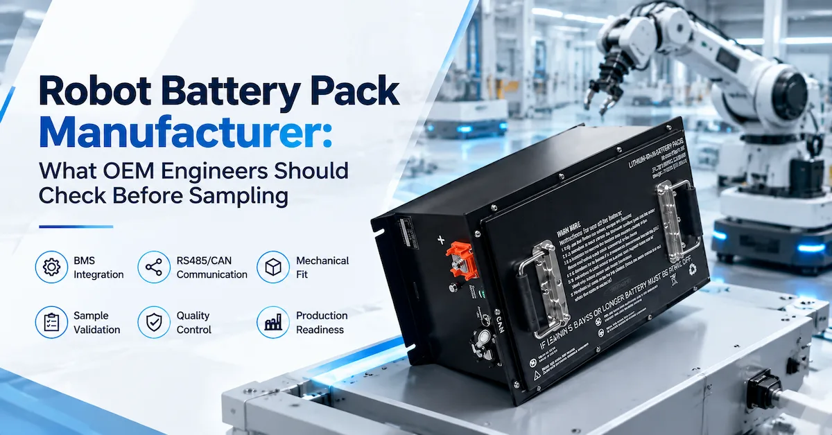
What Should a Robot Battery Pack with BMS Actually Prove?
Direct answer: A robot battery pack with BMS should prove four things before an OEM approves it: it can deliver the robot's continuous and peak load without unacceptable voltage sag; it can protect the cells and the machine under defined fault conditions; it can report usable state of charge (SOC) and state of health (SOH) in a way the controller can interpret; and it can repeat those behaviors from sample to production. Voltage and ampere-hours are only the starting point. The BMS, charger, controller, wiring, enclosure, firmware and mission profile must be treated as one power subsystem.
This is a commercial-investigation and RFQ question for robot OEMs, AMR/AGV integrators, warehouse automation teams and industrial equipment buyers. The practical decision is not "does this battery have a BMS?" Nearly every modern lithium pack has some form of battery management. The decision is whether the proposed BMS has the current capability, protection behavior, data interface and validation evidence required by the actual robot.
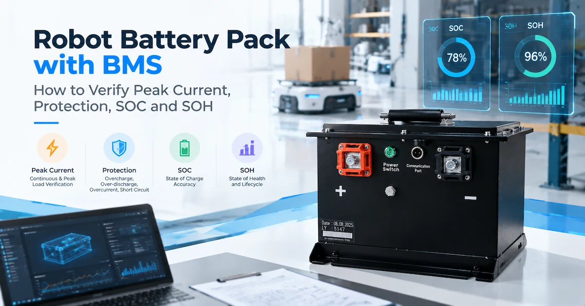
1. Start With the Robot Mission, Not the BMS Label
A BMS cannot be selected intelligently until the robot's work is described. A mobile robot may cruise at a modest current and then demand a short, sharp pulse when it accelerates, climbs a ramp, lifts a load, turns with a payload or recovers from an obstruction. An autonomous forklift can add regenerative events, hydraulic peaks and long idle periods. A warehouse AMR may use opportunity charging, while an inspection robot may spend most of its time at low load and depend on a stable reserve for a return trip.
Record the operating story
Give the battery supplier the robot mass, payload, wheel or drive arrangement, maximum speed, acceleration, route, floor condition, lift or actuator events, mission length, idle time, shift target, charging windows and reserve requirement. A current log is ideal. When it is not available, a timed description is still useful: "two drive motors, a three-second startup surge, one lift event every five minutes, six hours per shift, automatic charging during breaks." That statement is more valuable than a request for "a high-quality 48V battery."
Define the electrical window
Nominal voltage identifies a platform; the controller needs an allowed voltage window. Document the maximum charge voltage, normal operating range, controller undervoltage threshold, high-voltage response, startup voltage and any regeneration limit. The same nominal pack can behave differently in a robot if the controller shuts down early, the cable drop is high or the BMS opens the discharge path during a transient.
Separate confirmed facts from project assumptions
In an RFQ, mark each field as confirmed, measured, estimated or unknown. This prevents a provisional peak current from becoming an accidental production promise. It also gives the engineering team a clean list of measurements for the sample stage.
2. Understand Peak Current as a Time-Bounded System Requirement
Peak current is often the first reason a robot battery fails in the field. A data sheet may list a maximum continuous discharge value, yet the robot controller may need a higher current for a few seconds. Conversely, a supplier may quote an impressive peak number without stating the pulse duration, repetition rate, battery temperature, SOC, voltage sag or BMS reset behavior. Neither number is useful without conditions.
Continuous current and peak current answer different questions
Continuous current is the heat and energy condition the pack must sustain during the defined steady operating period. Peak current is a transient condition with a duration, a repetition pattern and a starting SOC. Write the requirement as a testable statement: for example, "120A for 3 seconds, repeated once every 60 seconds, from 80% to 20% SOC at the specified ambient temperature, with pack voltage above the controller minimum." The actual values must come from the robot, not from a generic example.
Check the complete current path
Cells are only one part of the path. The BMS switching devices or contactor, fuse, busbars, welds, cables, connectors and robot-side terminals all contribute resistance and heat. A pack can have enough cell capability but still show a large voltage drop at a connector or cable joint. Measure current and voltage at the battery output during the hardest event, and inspect temperature at the BMS, high-current joints and connector.
| Peak-current question | Why it matters | Evidence to request |
|---|---|---|
| How long is the pulse? | A 1-second event and a 30-second event create different thermal and voltage requirements. | Timed current trace, starting SOC, temperature and pass limit. |
| How often does it repeat? | Repetition determines heat accumulation and recovery time. | Mission profile or pulse sequence, not one isolated event. |
| What voltage is acceptable? | The controller may reset before the BMS reaches its protection threshold. | Minimum battery output and robot controller limit under load. |
| What happens at low SOC? | Resistance and available power can change as the pack discharges. | Pulse test at defined SOC points and temperature. |
Use load data instead of a guessed multiplier
Adding "30% margin" to an unknown current does not replace a load profile. If the robot is still in design, use the motor and controller data to build a first estimate, then instrument the prototype. Capture acceleration, lift, braking and docking events separately. The result should define BMS discharge limits, cable sizing, connector selection and acceptance tests together.
3. Review the Protection Architecture and Fault Recovery
Protection is not a single switch that makes a pack safe. It is a set of thresholds, delays, actions and recovery rules. A robot battery pack with BMS may need to protect against cell overvoltage, cell undervoltage, charge overcurrent, discharge overcurrent, short circuit, overtemperature and undertemperature. The robot also needs to know what happened and what it should do next.
Ask what each protection event does
For every protection item, document the trigger condition, delay, hysteresis, hardware action, communication alarm, reset method and whether the event is latched. An automatic recovery may be suitable for a brief current spike, while a detected short circuit may require a latched state and service inspection. The correct response depends on the machine hazard and operating procedure.
| Protection area | Engineering question | Robot-level check |
|---|---|---|
| Overvoltage | Does charging stop before the cell limit, and how is restart permitted? | Charger stops, alarm is visible and the pack recovers as specified. |
| Undervoltage | Does the pack prevent damaging discharge without trapping the robot? | Robot receives low-energy warning and can reach a safe dock. |
| Overcurrent or short | Is the trip fast enough, and is the event latched or recoverable? | Controller records a clear fault and service recovery is defined. |
| Temperature | Which sensors control charge and discharge, and what is the restart rule? | Robot reduces load or docks before a thermal shutdown. |
Protection must coordinate with the controller
A sudden BMS shutdown may be electrically correct but operationally dangerous if the robot loses steering, braking or communication in a narrow aisle. The integration plan should define warnings before a hard cutoff, the minimum reserve for a controlled stop, and the behavior after communication loss. Do not assume that the robot controller can infer a battery fault from one falling voltage signal.
Inspect the BMS hardware boundary
Ask whether the proposed BMS controls a MOSFET path, a contactor, a pre-charge circuit or another arrangement. Request current and voltage measurement points, balancing behavior, sensor locations and fuse coordination. The supplier does not need to disclose proprietary design details, but the buyer does need enough information to validate the system and service it safely.
4. Define SOC as an Operational Signal, Not a Decorative Percentage
State of charge is the battery's estimated remaining usable charge under defined conditions. In a robot, SOC is used for dispatch, return-to-charge decisions, low-energy alarms, fleet planning and operator displays. A percentage that looks precise but drifts from reality can cause missed missions or unnecessary charging.
Agree on what 0% and 100% mean
One project may define 100% as the end of a controlled charge and 0% as the BMS discharge cutoff. Another may reserve energy for a controlled return and display 0% before the cells reach the absolute limit. Both choices can work, but they must be documented. Include the charge completion condition, usable-energy window, reserve, calibration method and expected behavior after a partial charge.
Understand why SOC moves under load
Voltage falls during a high-current event because of internal and path resistance. If SOC is inferred from voltage alone, the robot may see an artificial drop during acceleration and an artificial recovery when the load ends. Current integration, voltage, temperature and periodic reference points are commonly combined, but the actual algorithm and calibration belong in the approved BMS documentation.
Test SOC where the robot makes decisions
Test the displayed SOC at startup, after a full charge, after an opportunity charge, during a peak event, at low SOC and after a protection event. Compare the BMS value with measured delivered capacity under a defined test. Record whether the controller receives the value in the expected units and timing. A SOC message that is numerically correct but delayed or scaled incorrectly is still an integration failure.
5. Treat SOH as a Trend With a Defined Baseline
State of health describes how the battery's present capability compares with a reference condition. It is not the same as SOC. SOC asks "how much usable charge is available now?" SOH asks "how has the pack's capacity or power capability changed from the agreed baseline?" For a robot fleet, SOH can support maintenance planning, warranty review and safe assignment of demanding missions.
Choose the SOH definition before comparing suppliers
SOH may be based on measured capacity, resistance, available power, energy throughput or a combination. A capacity-based percentage and a power-based percentage will not move in the same way. Ask the supplier to state the reference temperature, test current, usable voltage window, beginning-of-life baseline and update conditions. Without those definitions, two "90% SOH" values cannot be compared.
| Signal | Question it answers | What the buyer must define |
|---|---|---|
| SOC | How much usable charge remains in this operating window? | 0/100% points, reserve, calibration and display behavior. |
| SOH capacity | How much capacity remains versus the baseline? | Test current, temperature, cutoff and beginning-of-life capacity. |
| SOH power | Can the pack still deliver the required robot peak? | Pulse profile, voltage limit, resistance method and mission threshold. |
Do not use SOH as an unsupported lifetime promise
The public Dailymag product pages do not publish a universal cycle-life curve, warranty period or capacity-retention threshold. A responsible RFQ should therefore request the project-specific test method and acceptance limit rather than inserting a generic "thousands of cycles" claim. SOH becomes useful when the fleet owner knows what action follows a threshold: inspection, capacity test, role reassignment, replacement or removal from service.
6. Confirm RS485/CAN Data and Fault Ownership
A BMS-enabled robot battery is an electronic subsystem only when its data can be used by the robot. The physical presence of RS485 or CAN does not guarantee compatibility. The project needs a documented message map, units, scaling, update rate, alarms, permissions, wake-up behavior, communication-loss response and firmware revision.
Build a data dictionary
At minimum, identify pack voltage, current direction, SOC, SOH, temperature, cell or module alarms, charge permission, discharge permission, protection state and service information. State which values are read-only and which commands, if any, the controller may send. Include byte order, sign convention, units and timeout behavior in the controlled interface document.
Assign responsibility for the message layer
One party must own the final protocol definition. If the robot maker owns the controller, the battery supplier needs the interface requirement and test harness. If the battery supplier provides the protocol, the robot maker needs a stable revision, sample frames and a change-notification rule. Do not leave "CAN supported" or "RS485 available" as the entire requirement.
Review RS485 and CAN Integration
Test communication faults, not only normal messages
Disconnect the bus, introduce a delayed response, restart the controller, interrupt charging and recover from a BMS protection event. Confirm that the robot stops or docks safely, that the operator sees the correct alarm, and that communication resumes without a stale SOC or permission bit. A data link that works on a bench but fails during a restart is not production-ready.
7. Make the Charger Part of the BMS Requirement
Charging is where the pack, BMS and robot infrastructure meet. The charger must use the approved voltage and current profile, and the BMS must permit charging within the defined cell and temperature conditions. A robot may also need a charging handshake, docking interlock, contactor sequence or permission signal.
Review voltage, current and termination together
Do not choose a charger from the nominal pack voltage alone. Confirm maximum charge voltage, standard charge current, taper behavior, temperature limits, connector polarity and whether the charger is reused from an earlier battery. The public Dailymag robot platform lists 58V charge voltage and 20A standard charge, but those values must be checked against the controlled specification and the robot's charger before approval.
Test interrupted charging
Open and close the charging contact, remove AC input, move the robot away from the dock and reconnect after a BMS event. Check whether the charger and BMS recover in the intended order. Record start SOC, ending SOC, charge time, current taper, temperature and alarms. "It charged" is not enough to establish a repeatable fleet process.
8. Check Mechanical Fit, Thermal Paths and Service Access
BMS performance is affected by the physical pack. A sensor placed away from a warm joint may under-report temperature. A sealed enclosure may trap heat. A heavy pack can change robot handling and braking. A connector hidden behind a bracket can turn a simple service action into a long shutdown.
Release the interface drawing
Provide the maximum envelope, mounting points, insertion direction, restraint, connector keying, cable exit, bend radius, center-of-gravity limit and service clearance. Include tolerances and the cover or tray that will be used in production. The public robot platform lists dimensions of 498 x 305 x 90 +/- 0.5 mm and an approximate weight of 51.5 kg; use those values as a starting reference only and verify the production-intent drawing.
Measure heat at the places that matter
During the highest repeatable robot load and the hardest charge event, measure the BMS, high-current joints, connector, enclosure and representative cell or module locations. Compare the results with the agreed operating limits. A supplier may be able to change busbars, cable routing, sensor placement or enclosure details, but those changes should be documented and retested.
9. Validate the Pack in Four Layers
A convincing validation plan moves from controlled measurements to robot missions. Each layer answers a different question. Skipping the robot layer leaves integration risk; skipping the production layer leaves repeatability risk.
Layer 1: identity and fit
Check model, revision, serial or lot, label, dimensions, mass, mounting, connector, cable routing and removal. Confirm that the BMS configuration loaded in the sample matches the quotation and protocol document. Photograph the installed sample if the fit is difficult to reproduce.
Layer 2: electrical and protection baseline
Measure open-circuit voltage, charge behavior, capacity or energy under a defined method, standard discharge, continuous load, peak pulse, voltage sag and temperature. Trigger the agreed protection events with appropriate test equipment. Record the recovery action and communication alarm. Keep raw files, instrument identifiers and test conditions.
Layer 3: controller and charger integration
Connect the intended robot controller, charger and display or fleet gateway. Verify startup, sleep, wake-up, charge permission, discharge permission, SOC, SOH, alarms, communication timeout and reset behavior. Test the exact firmware or parameter revision intended for the pilot.
Layer 4: representative mission
Run the robot with payload, route, acceleration, lifting, waiting, docking and charging behavior that represent the target deployment. Use a production-intent sample, not a laboratory pack with temporary wiring. Capture mission cycles, current, voltage, SOC, temperature, alarms, charging time and reserve. The acceptance report should state pass/fail limits and deviations.
10. Use Public Product Evidence Without Overreading It
Public specifications are valuable for screening, but they are not a substitute for a controlled project data sheet. The current Dailymag 51.2V 108Ah robot battery page publicly lists the following fields:
| Public field | 51.2V 108Ah page value | What still needs confirmation |
|---|---|---|
| Nominal voltage | 51.2V | Robot operating window and controller limits. |
| Rated capacity | 108Ah | Test method, usable energy and reserve. |
| Charge | 58V charge voltage; 20A standard charge | Approved charger profile, temperature limits and permissions. |
| Discharge | 50A standard; 150A maximum continuous | Peak pulse duration, SOC, temperature, voltage sag and complete current path. |
| Communication | RS485/CAN | Protocol, message map, alarm definitions, timing and controller test. |
| Dimensions and mass | 498 x 305 x 90 +/- 0.5 mm; 51.5 kg | Production drawing, tolerance stack, center of gravity and installed fit. |
| Energy field | Page displays 5.53Wh | Unit and value require engineering confirmation before quoting or publishing. |
The energy field is intentionally shown as a confirmation item. It should not be silently "corrected" in marketing copy, even though voltage multiplied by ampere-hours suggests a different order of magnitude. A buyer should request the latest controlled datasheet and ask which test conditions define rated energy.
11. Evaluate Factory Evidence and Production Control
A robot battery pack with BMS is not production-ready because one sample reports the right numbers. The manufacturer must be able to reproduce the electrical configuration, BMS settings, mechanical build, labels, test limits and packaging across the intended lot.
Request a configuration-controlled package
Ask for the approved specification, drawing, bill-of-material boundary, BMS parameter revision, communication document, charging requirement, inspection plan, end-of-line test list, acceptance limits and change-notification process. The documents should identify the model and revision. A generic battery report with no serial or lot connection is weak evidence.
Map public services to evidence
Dailymag publicly describes product design, sampling, R&D, quality management from raw-material transportation through preprocessing, production and before shipment, packaging, logistics and after-sales support. Its service information also describes sampling checks at four production stages and planning ranges of approximately 15-30 business days for standard customization or 45-60 business days for projects requiring more R&D and testing. These are useful process signals, not automatic proof that every robot project has completed the same tests.
Control changes after sample approval
Cell or module substitution, BMS firmware, protection parameters, connector, cable, enclosure, label or packaging can change robot behavior. Define which changes require buyer approval and revalidation. Link the delivered serial or lot to the approved revision and final test record. That traceability becomes especially important when a fleet reports an SOC drift or a peak-current trip months after launch.
12. Prepare an RFQ That Makes BMS Capability Comparable
Supplier comparisons become unreliable when each bidder interprets the robot differently. Use one RFQ template and require assumptions to be visible. The following fields give an engineering team enough context to compare a standard platform, a modified pack and a fully custom design.
- Robot identity: model, mass, payload, drive system, route, speed, acceleration, lift events and deployment environment.
- Electrical load: nominal voltage, allowed voltage window, average current, continuous current, peak current, pulse duration, repetition and regeneration.
- Energy target: shift time, mission cycles, reserve, usable-energy window, end SOC and opportunity-charging plan.
- Charger: model, output voltage and current, connector, dock behavior, charge time, communication and whether the charger is retained.
- BMS: protection functions, sensor locations, current path, SOC/SOH definitions, alarms, wake/sleep behavior and reset rules.
- Communication: RS485 or CAN, physical wiring, protocol owner, message map, units, update rate, timeout and firmware revision.
- Mechanical package: envelope, mounting, mass, center of gravity, connector location, cable route, service clearance and removal method.
- Environment: operating and storage temperature, charging temperature, vibration, shock, dust, water, condensation, altitude and cleaning method.
- Validation: sample quantity, robot availability, mission profile, instruments, raw-data format, pass/fail limits and deviation approval.
- Commercial plan: prototype and pilot quantities, forecast, MOQ, tooling or NRE, packaging, destination, Incoterm and schedule assumptions.
Ask every supplier to identify unknowns and exclusions. A quotation that clearly states "protocol register map to be supplied after controller review" is easier to manage than a vague promise of compatibility. Send photos of the battery bay, current logs, charger label, controller and any field fault when contacting Dailymag through the contact page.
13. Red Flags Before Approving a BMS-Enabled Robot Battery
- The supplier recommends a pack from nominal voltage and Ah without asking for the robot duty cycle or controller minimum voltage.
- Peak current is quoted without pulse duration, repetition, SOC, temperature, voltage sag or cable and connector conditions.
- Protection thresholds are listed without delays, hysteresis, latching and recovery behavior.
- SOC and SOH appear on a screen, but their reference points, units and update behavior are not defined.
- RS485/CAN is treated as a compatibility guarantee without a protocol document and controller test.
- The charger is selected only from the nominal battery voltage, with no charge permission or interrupted-charge test.
- The sample passes a bench load but is not tested during acceleration, lifting, docking and return-to-charge behavior.
- A product page value is copied into the RFQ even though the unit, test condition or version is inconsistent.
- Cell, BMS, firmware, connector or enclosure substitutions are allowed without a change review.
- The supplier cannot connect the delivered pack to a serial, lot, revision and production test record.
An open item is not automatically a rejection. Industrial projects often begin with incomplete load data or a controller that is still changing. The useful question is whether the supplier identifies the gap, proposes a measurement or document, assigns an owner and updates the controlled specification when the result is known.
Frequently Asked Questions
What does a BMS do in a robot battery pack?
The BMS monitors electrical and temperature conditions, applies defined protection actions, estimates SOC and possibly SOH, and communicates status or permissions to the charger and robot controller. The exact functions depend on the selected hardware, parameters, firmware and project interface document.
Is a high maximum continuous current enough for robot peak load?
No. Maximum continuous current is not a complete peak specification. The robot buyer must define pulse duration, repetition, starting SOC, temperature, voltage sag, controller minimum voltage and the ratings of the BMS switching path, fuse, cables and connectors.
Why can SOC drop suddenly when a robot accelerates?
High current causes temporary voltage drop and can expose the limits of a voltage-based estimate. The BMS may combine current, voltage and temperature data, but the behavior still needs to be tested at the load events where the robot makes decisions. The controller should use agreed alarms and reserve rules rather than reacting to one unstable percentage.
What is the difference between SOC and SOH?
SOC estimates usable charge remaining now. SOH compares present capacity, resistance or power capability with an agreed beginning-of-life reference. SOC supports immediate dispatch and charging decisions; SOH supports maintenance, fleet planning and end-of-service decisions.
Does RS485/CAN prove that the BMS will work with my robot?
No. It identifies a physical communication option, not a complete interface. Confirm wiring, message map, units, timing, alarms, permissions, timeout behavior, firmware revision and the test procedure with the intended controller and charger.
Should the BMS protection limits be copied directly from a standard pack?
No. Limits depend on cell or module configuration, charger, current path, robot controller, temperature, enclosure and operating risk. A standard platform can be a starting point, but production limits and recovery behavior should be approved for the actual robot.
Is Dailymag's 51.2V 108Ah robot platform a universal solution?
No. The public page provides a useful reference with 51.2V nominal voltage, 108Ah rated capacity, 58V charge voltage, 20A standard charge, 50A standard discharge, 150A maximum continuous discharge, RS485/CAN, dimensions of 498 x 305 x 90 +/- 0.5 mm and approximately 51.5 kg. Suitability still depends on the robot's voltage window, load, charger, communication, fit and validation. The public energy field also requires confirmation.
What factory documents should accompany a BMS-enabled sample?
Request the controlled specification, drawing, BMS parameter revision, communication document, charger requirement, protection test results, SOC/SOH definitions, sample serial or lot, inspection record, deviations and change-control rules. Add the production test plan before approving a pilot lot.
How long can robot battery customization take?
Dailymag's public service information gives planning ranges of approximately 15-30 business days for standard customization and 45-60 business days for projects requiring more R&D and testing. The final schedule depends on design completeness, materials, sample quantity, test scope, buyer approvals, packaging and shipping. It should be confirmed in the project quotation.
What should I send for a robot BMS review?
Send the robot model, battery-bay drawing or photos, voltage window, current log or motor/controller data, peak event description, runtime and reserve, charger, communication requirement, environment, sample quantity, forecast and destination. Mark unknown values as unknown; that helps the engineering team separate assumptions from requirements.
Conclusion
A robot battery pack with BMS should be approved as a controlled power subsystem, not as a box that happens to contain cells. Peak current must be expressed as a timed and repeatable event. Protection must include thresholds, delays, alarms and recovery. SOC must support real operating decisions, while SOH must use a defined baseline and action threshold. RS485/CAN must be backed by a data dictionary and controller test. The charger, mechanical package, thermal path and production records are part of the same decision.
Dailymag's public robot platform and its services for product design, sampling, R&D, quality management, packaging, logistics and after-sales support provide a practical starting point for an OEM discussion. Final approval should rely on the latest controlled specification, configuration-specific BMS information, production-intent sample, representative robot mission, traceable test records, agreed MOQ and lead-time assumptions, and a change-control process.
For a project review, send the robot load story, battery-bay drawing, charger and controller details, required SOC/SOH behavior, RS485/CAN documents, validation plan and forecast. The Dailymag contact page can route the information to the appropriate engineering and quotation review.