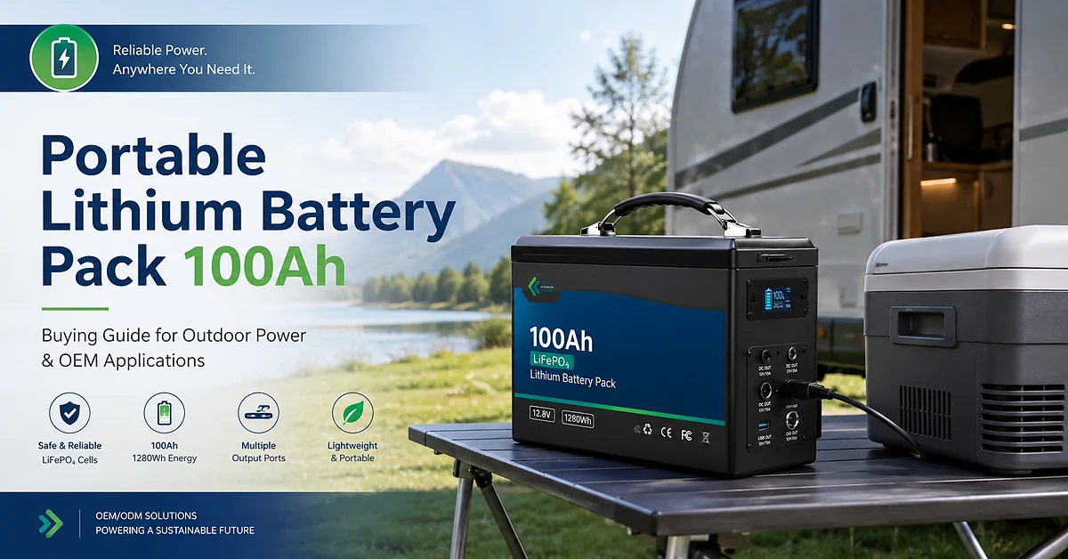
Lithium Battery Pack for OEM Systems: Product-Level Solutions That Reduce Integration Risk
In OEM projects, battery-related failures rarely originate from chemistry choices. They emerge when a lithium battery pack fits specification sheets but fails to align with real system constraints such as enclosure limits, thermal behavior, communication logic, or maintenance strategy. These gaps usually surface late—during commissioning or early operation—when changes are expensive and schedules are already under pressure.
This article focuses on how OEM teams can translate known risks into concrete product decisions that are executable, verifiable, and scalable.
Electrical Performance Issues — Solved Through Clear Product Parameters
Typical issue
Systems experience voltage instability, unexpected current limiting, or premature protection triggers even though nominal ratings appear sufficient.
Product-level solution
OEM-ready battery products resolve these issues by defining parameters that reflect real operating conditions:
-
Operating voltage window instead of nominal voltage only
For example, 48V-class systems typically require a stable working range (such as ~43–54V) that matches inverter tolerance. -
Continuous discharge capability aligned with load profile
A 100Ah pack rated at 1C continuous supports sustained operation far better than designs optimized only for short peak current. -
Consistent cell matching and balancing logic
Proper grouping reduces internal imbalance, improves voltage stability, and extends usable service life.
These specifications should be explicitly confirmed in product documentation before system validation begins.
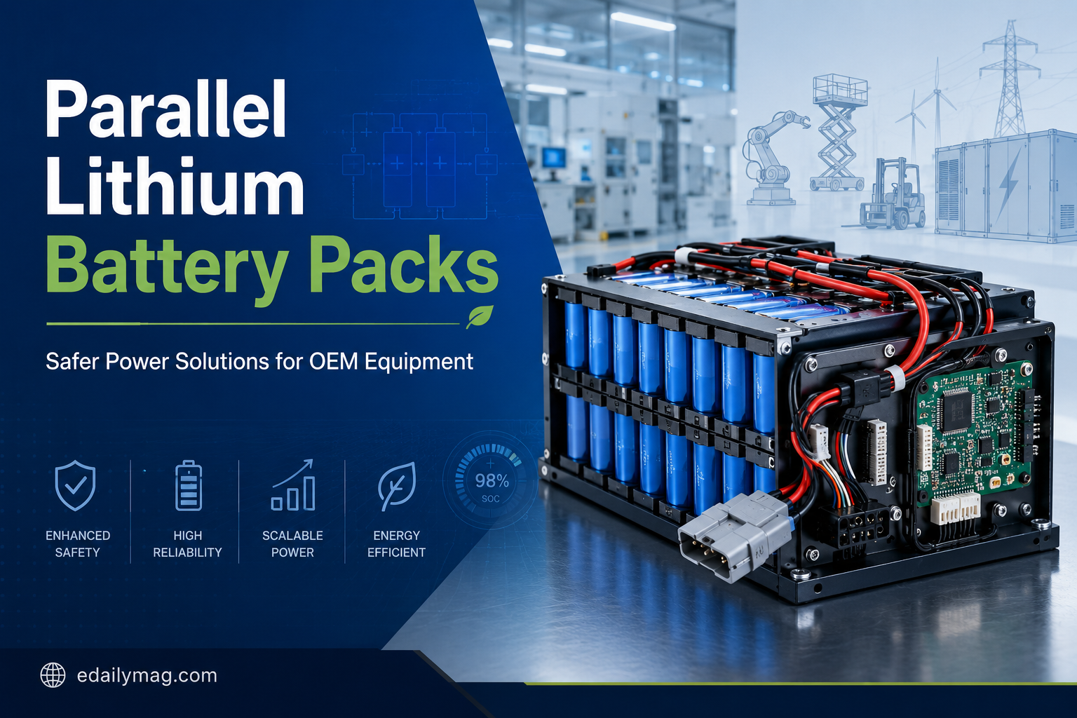
Mechanical and Structural Challenges — Addressed by Modular Product Design
Typical issue
Battery solutions pass electrical tests but fail mechanically due to vibration, heat accumulation, or difficult service access.
Product-level solution
A well-designed lithium battery pack integrates structural features that support long-term OEM operation:
-
Modular internal layout, improving airflow and simplifying partial service
-
Reinforced enclosures, commonly 1.2–2.0 mm steel or aluminum depending on vibration exposure
-
Standardized mounting points, aligned with cabinet or chassis structures
These design choices reduce mechanical stress on cells and busbars while improving overall system durability.
BMS Integration Challenges — Solved Through Configurable Control Logic
Typical issue
OEM projects are delayed when battery communication or protection logic conflicts with system controllers.
Product-level solution
Instead of fixed firmware behavior, OEM-oriented battery solutions should provide:
-
Selectable communication interfaces (CAN, RS485, Modbus)
-
Adjustable protection thresholds aligned with system load and environment
-
Accurate SOC and SOH estimation, especially under partial and variable load
Configurability at the BMS level significantly reduces commissioning time and repeated firmware revisions.
Standard Platform + Targeted Customization: A Controlled OEM Strategy
Typical issue
Full customization inflates cost and lead time, while purely standard products introduce integration compromise.
Product-level solution
Most OEM programs benefit from a controlled configuration strategy:
| Product Aspect | Platform-Based | Targeted Adaptation |
|---|---|---|
| Electrical architecture | Fixed | Fixed |
| Enclosure & connectors | Standard | Adapted |
| BMS communication | Default | Configurable |
| MOQ & delivery | Predictable | Managed |
This approach limits validation scope while addressing system-critical requirements.
Procurement and Delivery Risks — Reduced by Transparent Product Data
OEM teams should base sourcing decisions on concrete data rather than assumptions.
Recommended data to request includes:
-
Configuration-specific MOQ, not generic minimums
-
Lead time breakdown, covering cells, assembly, and testing
-
Factory test scope, including electrical safety, insulation, and communication checks
Suppliers who provide this information clearly tend to support smoother project execution and fewer late-stage changes.
Common OEM Battery Configurations Used in Practice
Although applications differ, several configurations dominate OEM deployments:
| Application | Nominal Voltage | Capacity Range | Design Priority |
|---|---|---|---|
| Industrial equipment | 48V | 40–200Ah | Structural robustness |
| Energy systems | 51.2V | ~100Ah | Communication stability |
| Mobile OEM platforms | Custom | System-defined | Weight and form factor |
Selecting established configurations simplifies integration and shortens validation cycles.
Common OEM Questions
Q1: How can I verify real operating performance before mass production?
Focus on continuous current ratings, operating voltage range, and thermal design rather than peak specifications alone.
Q2: Which product features most affect long-term maintenance cost?
Modular structure, accessible connectors, and configurable BMS logic typically outweigh differences in nominal capacity.
Q3: How can customization be limited without sacrificing compatibility?
Fix the core electrical architecture and customize only enclosure, connectors, and communication interfaces.
Why OEM Teams Choose eDailyMag
eDailyMag provides OEM-oriented battery solutions designed around real system constraints, not generic consumer use cases.
Key strengths include:
-
Product architectures aligned with enclosure, communication, and operating requirements
-
Configurable BMS and interface options that reduce integration effort
-
Transparent MOQ, lead time, and test scope for predictable planning
OEM teams can review available product options and system configurations at
👉 https://www.edailymag.com/
For project-specific discussions—such as parameter matching, enclosure adaptation, or delivery scheduling—you can directly connect with the engineering team via
👉 https://www.edailymag.com/contact-us